Corner echoes are widely used in NDT for surface breaking cracks detection in metal components exposed to fatigue and/or corrosion cracking. The use of simulations in order to evaluate and optimize the detectability of these cracks is of great interest and support for industries.
The following configurations contributed to the validation of CIVA predictions of corner echoes associated with rectangular notches. The acoustic paths associated with corner echoes are illustrated in the next figure:
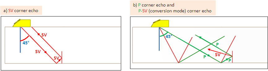
The corner echo corresponds to the double reflection of an oblique incident bulk wave on the specimen backwall and on the notch. Mode conversion can also occur which gives rise to additional corner echoes.
The geometrical configuration strongly influences the corner echoes. Their amplitude varies with the following parameters:
- (SV and P) refraction angle in the mock-up
- Beam divergence (i.e. probe aperture), affecting refracted angles contained in the beam radiated through the mock-up
- Probes central frequency relatively to the notch size and to the bandwidth
- Defect depth and location in the field profile relatively to the maximal amplitude of the field
- Angles between the specimen backwall and the flaw (tilt, skew)
- Flaw dimensions (height and length)
Depending on the NDT configuration, the relative importance of these parameter may vary. Typically, the simulations validation requires variation of each influent parameters separately in order to be able to discriminate their contributions and the potential sources of discrepancy with experiments.
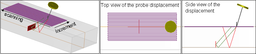
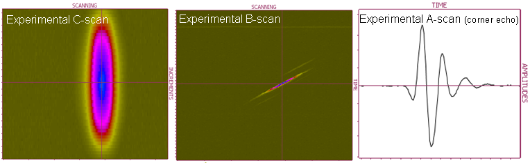
In the following configurations, inspections are performed with a probe generating SV waves in planar, homogeneous and isotropic specimens containing vertical backwall breaking notches; tilted notches will be dealt in another study. A scanning is performed along X and Y axes. Experimental acquisitions are performed using a device consisting of a mechanical bench able to display C-scan representations, and an ultrasound phased array acquisition system MultiX 64 controlled by the software Multi2000 V6.5.22.
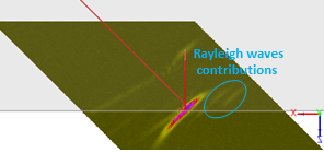
Contributions associated with Rayleigh waves (circled in blue) are not computed with the semi-analytical model of CIVA but they are taken into account with the Transient Finite Element Model (TFEM) available since CIVA 2020 and in the module CIVA ATHENA 2D. Contributions associated with diffraction are calculated by CIVA but are not studied in this validation work.
The TFEM is an automatic hybrid model strategy based upon a reciprocity relation where the incident fields are computed using a ray-based method while the diffracted field is locally computed around the defect using a numerical method. The main differences with Athena hybrid method are twofold: first the numerical solver is built upon a “dedicated” high-order spectral finite element method, which enables us to address 3D configurations, and second, the constitution of the numerical parameters are automatically deduced from the CIVA configuration, leading to a diffraction model that can be manipulated through the GUI similarly to the GTD or Kirchhoff models.
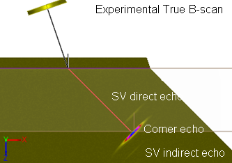
In this document, the comparisons are performed on the corner echo amplitude. However, results interpretation may also require the analysis of A-scans, B-scans, C-scans or echodynamic curves.
The measurements are referenced relatively to the response of a Side-Drilled Hole (SDH). Indeed, it is a reflector commonly used for calibration and which specular echoes are simulated very precisely by CIVA (see SDH prediction with CIVA)
Continue to Synthesis of validation cases
Back to Corner Echoes with SV mode
Back to Corner Echoes