Link parameters during parametric studies
In the frame of development, expertise or qualification processes in NDT, parametric studies will be necessary to study the impact of influential parameters on your inspection’s outcome. A simulation software such as CIVA is particularly well suited to run parametric studies in NDT, as it provides the ability to precisely monitor input parameters and then explore a wide range of situations in a limited time. The possibility to generate a metamodel from a database of simulated cases will also let the user access any combination of parameters’ values, which can be very efficient, especially in the case of many potential influential parameters (see this video).
For multiparametric studies, it may be necessary to link some parameters together. Indeed, some parameters can be correlated by nature, which means they cannot vary independently from others (for example, length and height of a crack are usually linked). You may also wish to focus on some specific combinations or reduce the number of independent parameters to limit the amount of simulations to perform, or iterate on specific influential parameters obtained from the combination of different inputs (for example, the surface of a flaw). To do that, CIVA provides the possibility to define formulae allowing to link one parameter to another, variable one.
Let’s take the example of a weld inspection scenario, where you wish to study the results obtained for different defects located in the Heat Affected Zone (HAZ).
Due to the weld chamfer profile, moving the flaw in the HAZ will require linking the flaw depth and the flaw’s axial position. This is possible in CIVA with a formula.
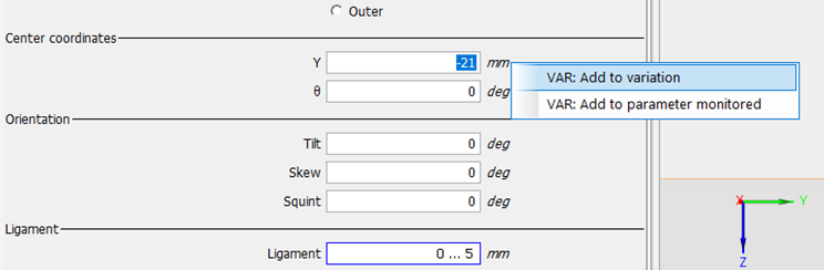
First, you define both parameters as variables, by selecting them with the relevant contextual menu in the flaw panel.
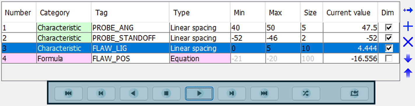
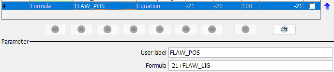
In the Variation panel, the flaw ligament (called “FLAW_LIG” here) is monitored with a linear spacing of 10 values between 0 and 5 mm. It corresponds to a “characteristic” type of variable in CIVA. By selecting the type “Formula” for the flaw’s Y position parameter (named “FLAW_POS” here, which corresponds to the distance to the weld’s center), you can then key in a mathematical relationship between this parameter and the previous one. Note that two other parameters were involved in this example of parametric study: the probe’s refraction angle and the probe’s standoff (distance to the weld center).
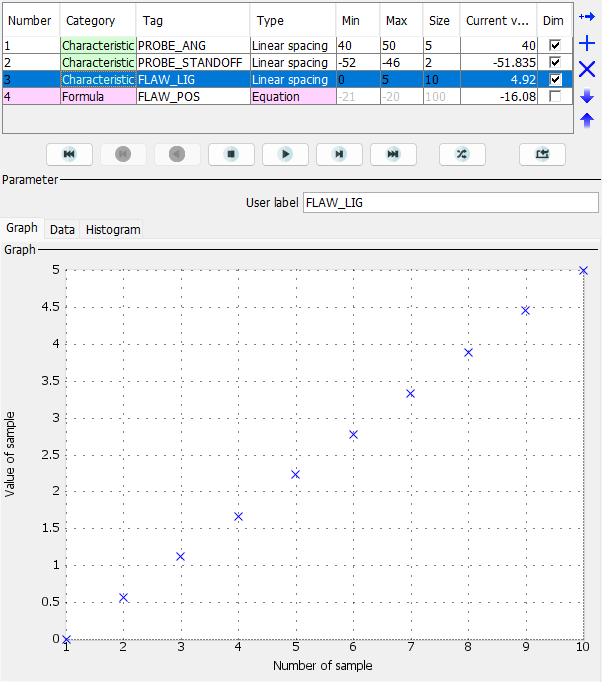
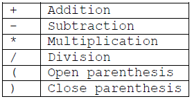
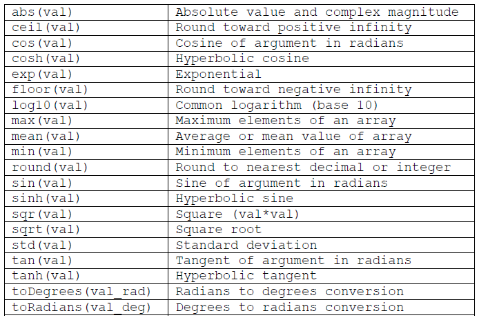
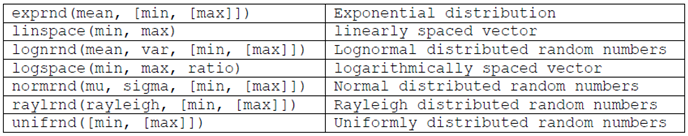
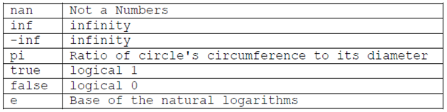
To do so, each parameter can be used in a formula with their TAG name (customizable by the user) and mathematical operators are available to build your formula (see tables hereafter). In this application case, a simple linear function “-21+FLAW_LIG” has been entered to monitor the flaw’s position along the HAZ depending on its depth, but you have of course many other possibilities!
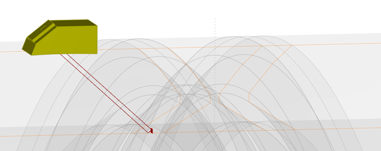
To make sure that you have defined relevant formulae, you can use the preview buttons in the Variation tab to check in the 3D view that the defined variations are consistent with your design of experiments.