Define tilted flaws in Civa ET
In CIVA ET Inspection Simulation (3D) module, there are some limitations on the flaw orientation when using canonical geometries (plates, tubes). Thus, in this module, with simple parametric components, the flaw tilt cannot be modified, and computations can only be carried out for flaws perpendicular to the specimen surface.
Since CIVA 2023, it is possible to define complex shape components in the Inspection Simulation (3D) module. These complex shape components can be obtained either from predefined geometries (blade root or groove, weld profiles) or from a 2D CAD profile extrusion. Some examples of complex geometries can be seen below.
 Rib under plate (CAD defined) |
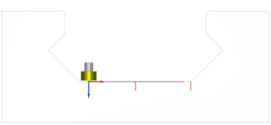 Blade groove |
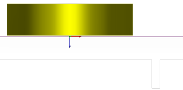
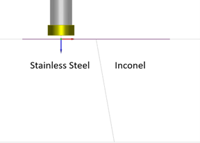 Bimetallic plate (CAD defined) |
Contrary to canonical geometries, for which the simulations are managed by a semi-analytical method with reduced computation times, but for which there are some limitations, complex components are solved with a numerical method (“FIT” method, for “Finite Integration Technique”) through which there are less limitations on the shape of the component, but also on the flaw orientation, which is no longer necessarily perpendicular to the component surface.
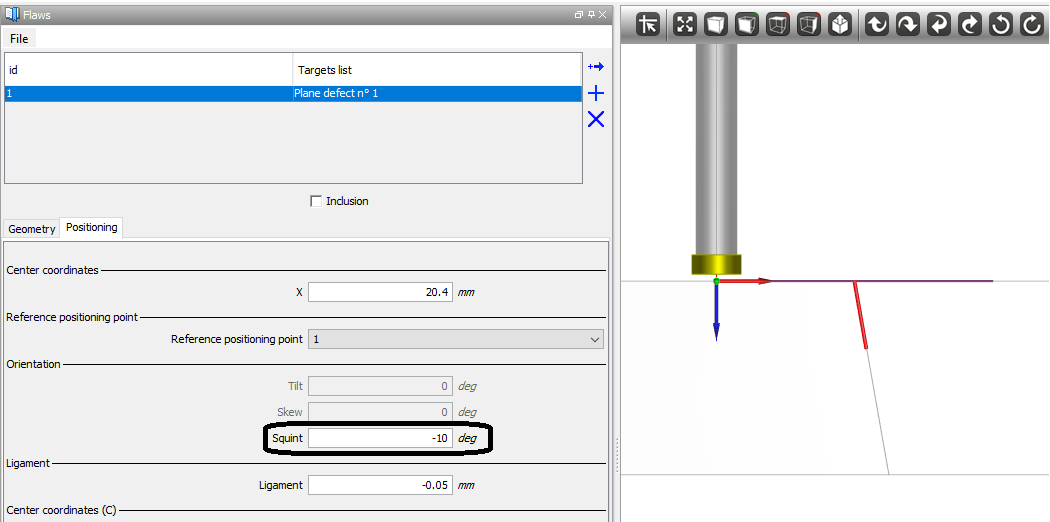
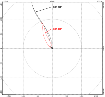
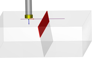
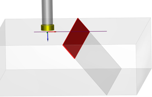
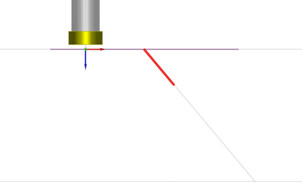
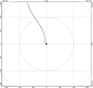
Although with this type of component, in CIVA 2023, the plate and flaw geometry is considered as invariant in the extrusion direction, it is now possible to study the impact of the flaw tilt on the measured signal. Results below show the signal obtained for two flaw tilt values: 10° and 40°. And if you want to modify the flaw tilt in a simple plate, you just have to define the specimen geometry as a 2D CAD one and you will be able to control this angle.
| Tilt 10° | Tilt 40° |
 |
 |
 |
 |
 |
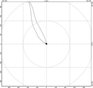 |
The superimposed curves are visible on the following picture, that shows the impact of the flaw tilt on the amplitude, the phase and the shape of the measured signal.