
Automatic and fast computation of TCG calibration curves for inspection configuration with single and multi-elements probes
It is possible with CIVA 2020 SP3 to quickly compute an automatic TCG calibration procedure before the simulation of the studied inspection configuration. From the “Simulation settings > Calibration” panel, CIVA users can select the “Computed TCG (from SDH echoes)” calibration type, and define the relevant TCG calibration procedure to compute considering the calibration block (material, thickness) and defects (list of side-drilled holes with given diameter and depths). Once the calibration is computed in the CIVA interface, calibration data (shots, times of flight, amplitudes) can be exported in a text file, and visualized in TCG tables and curves for each side-drilled hole depth and each acquisition sequence and shot as defined by the user in the phased-array settings of the studied probe.
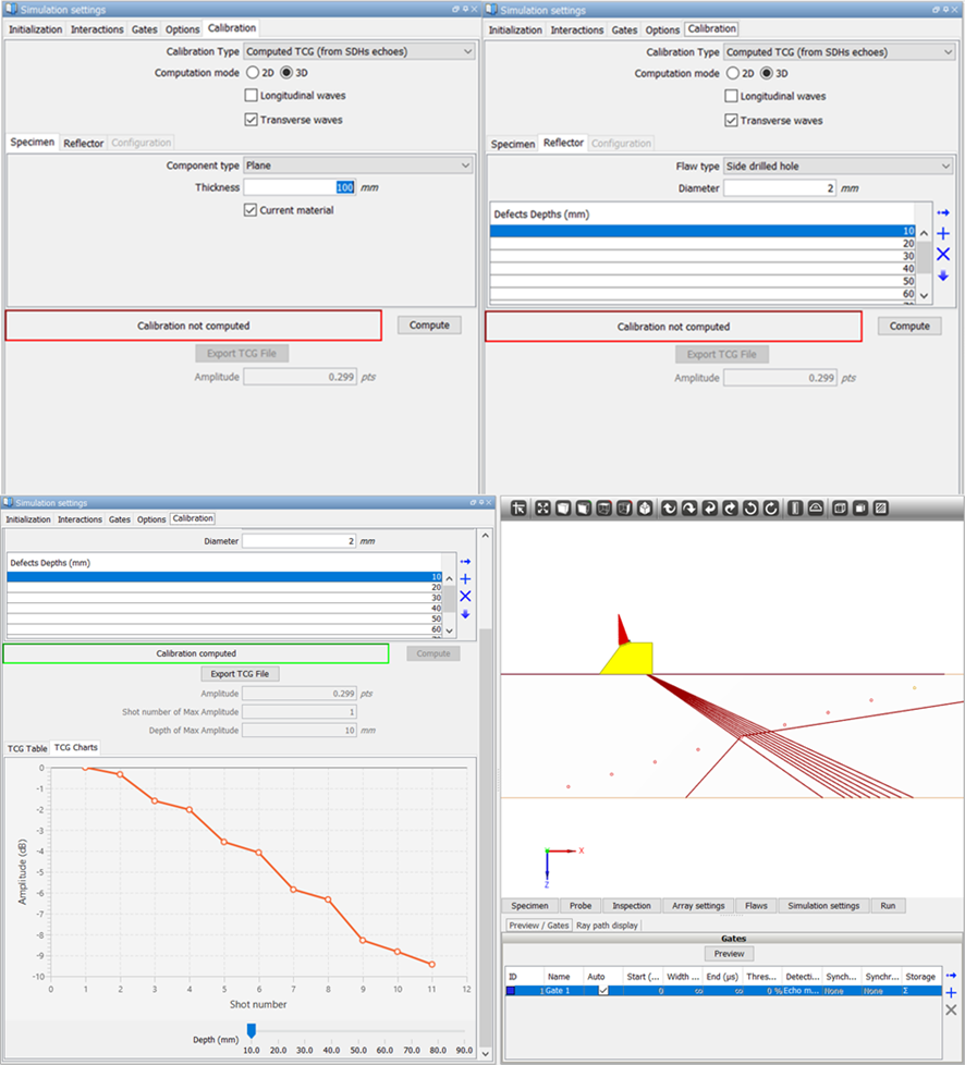
Automatic computation of TCG calibration from the “Simulation settings > Calibration” panel
Once the calibration is defined and computed, the user can run the computation of the studied inspection configuration, and the output results will be automatically calibrated considering the computed TCG data. The figure below displays an application example of CIVA TCG computation, used for a 16 elements probe inspecting a calibration block with 9 side-drilled holes of 2mm diameter located at depths: 10mm, 20mm, 30mm, 40mm, 50mm, 60mm, 70mm, 80mm, 90mm.
In this simulation, the probe acquisition settings define a sectorial scanning from 55° to 65° with 1° step, and the computed TCG settings are identical to the simulated inspection configuration. By comparing the results obtained with and without computed TCG calibration option, the simulated SDH responses are well rectified to 0dB with computed TCG calibration for all the shots of the acquisition sequence and all the defect depths.
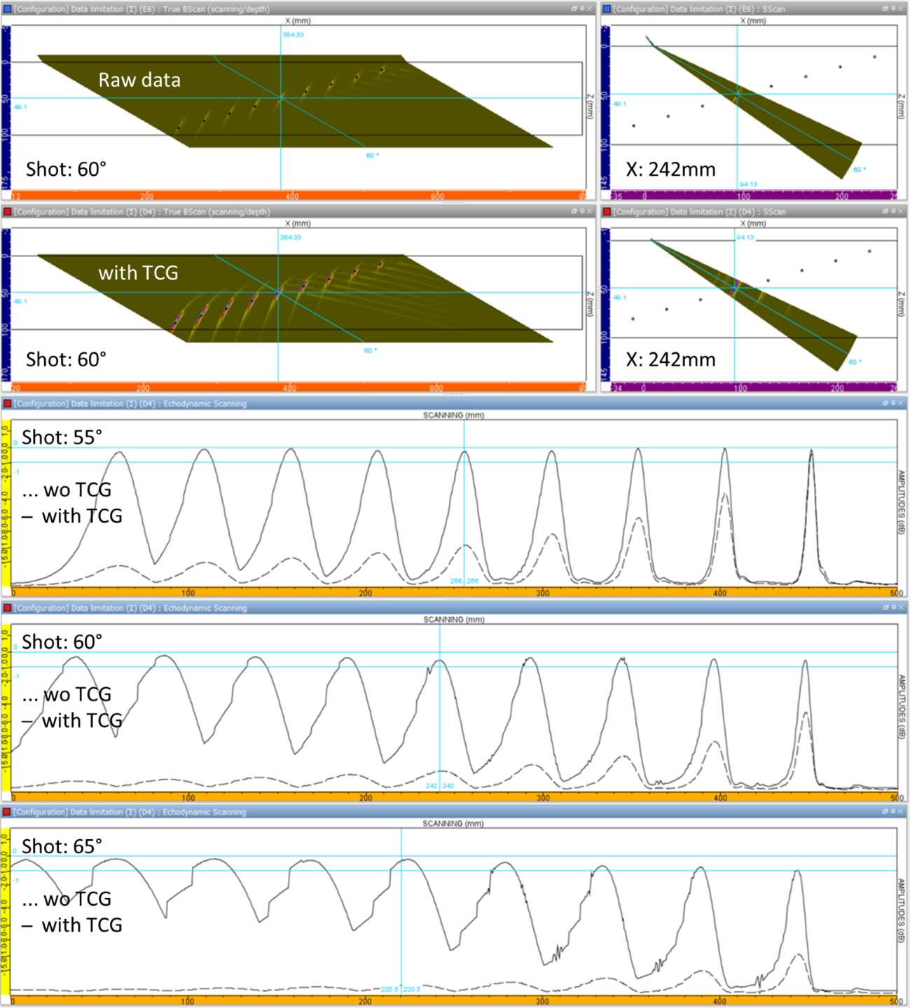
Simulation of a calibration block with a 16 elements linear probe with and without TCG simulated calibration
During the calibration pre-computation, CIVA automates beam computations (with 2D or 3D options) in ideal/simplified configurations, in order to build in almost real-time and with reasonable accuracy the calibration TCG curves to use for inspection configuration simulation. Considering the simplifications, such automatic calibration computation can be less accurate compared to the exact calibration procedure simulation, when the ultrasonic beam is steered compared to its geometrical rays of main energy, as illustrated in this example, with a maximal calibration error of 1.2 dB for the closest depths to the entry surface (near field) and the highest refracted angles (beam deviation). Such errors appears reasonable considering the computation performances of such calibration tools, allowing you to compute the TCG data of a phased-array probe with large numbers of acquisition sequences and side-drilled hole depths in less than a minute with a conventional computer in most complex application cases.
Please note that the user can also extract the TCG calibration data of single and multi-element probes in a text file to understand its structure, potentially modify its calibration values, and load the new calibration file as simulation results post-processing calibration of an inspection configuration.