How to display the corner echo at its correct location
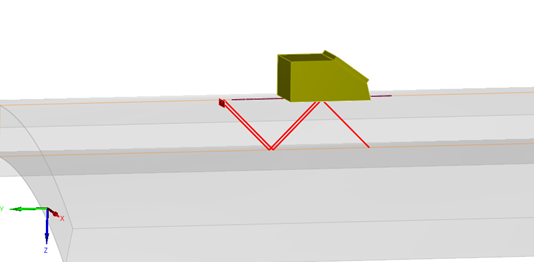
By default, the reconstruction of the B-Scan image in the 3D view is performed according to the direct ray paths. For instance, when running a simulation with “half-skip” mode option, the reconstructed B-Scan is automatically displayed as follows:
What happens now if the flaw is an outer breaking notch, and a “full skip” option is required to correctly model the configuration?
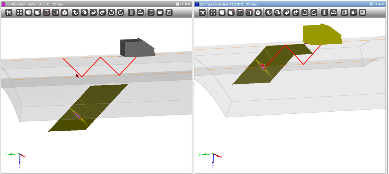
The figure below represents an inspection with a T45° probe angle with an outer breaking notch:
As visible below, the reconstructed B-Scan in the 3D view displays by default the main corner echo of the flaw outside the specimen.
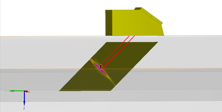
From the tool box, in the Options tab and in Visualization properties, by selecting the number of reflections, raypaths can be reflected after reaching the backwall or the surface. The true view in this case is the sum of a direct and a reflected image.
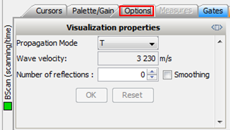
It is then possible to choose the number of skips wanted to account for in the image, and simply click on “OK” to apply. A reconstruction with one reflection is displayed below.
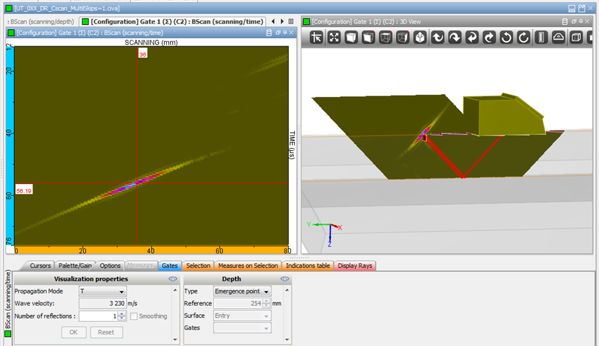
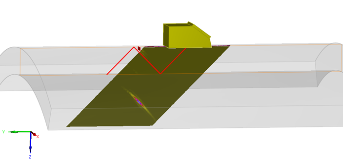
Multiple skips reflection is also possible with a large number of reflections.