
Definition of an “FE grid” flaw
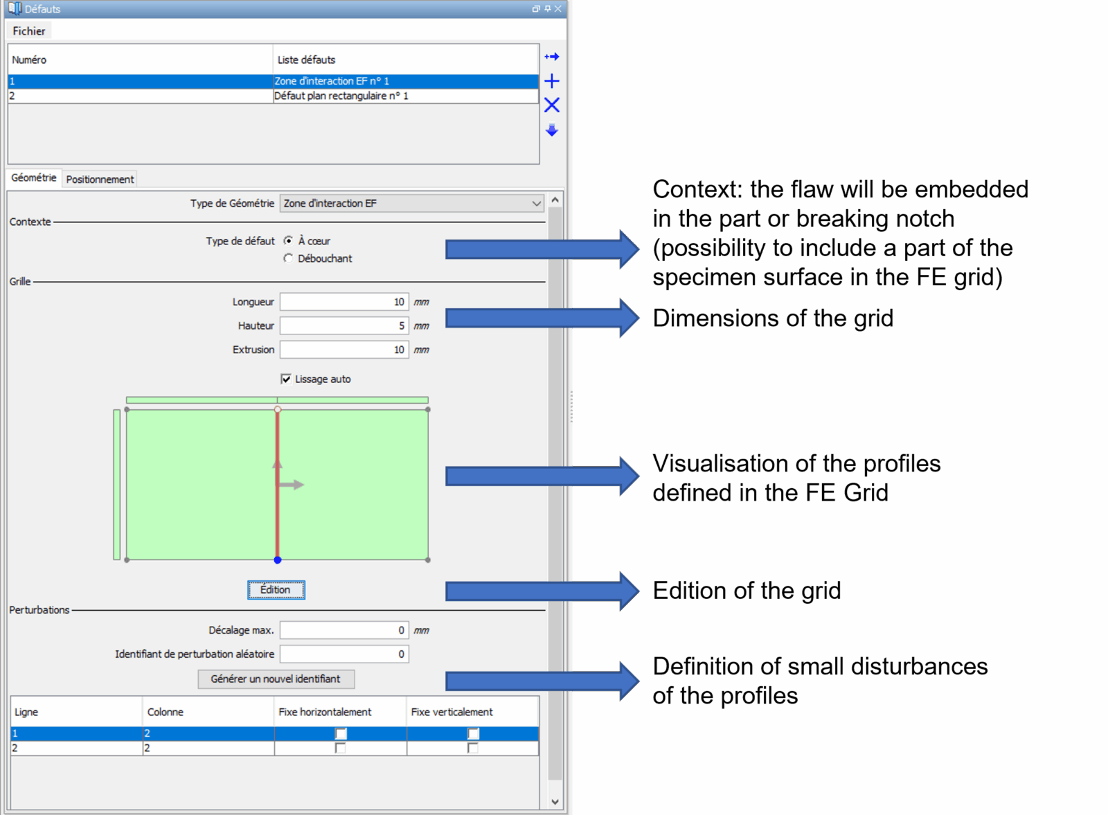
Do you want to perform a simulation with finite element models in CIVA? The first thing to do is to select the “FE interaction zone” option in the “Geometry” dropdown list.
Before drawing the profile of this defect from the grid editor, it is necessary to define the “context”, in order to know if this defect will be considered as embedded in the part or “border”, i.e. outer or inner flaw (and therefore if the geometry of the part will be partially included in the finite element calculation area).
It is then necessary to enter the dimensions of the 3D zone in which the defect will be created (this zone must include all the defect(s) accounted for: the defect can be smaller than the zone, its extrusion will be of the dimension of this one. The user may also define small disturbances to be applied to the profiles drawn).
Predefinition of the grid and of the FE flaw
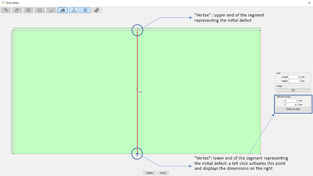
The next step consists in drawing the different profiles of the defect(s). You must therefore enter the editor (Edit the grid sketch) and draw the relevant profile segment by segment (from predefined “vertex”, see screenshot below). The grid is initialized with a red line in the center, which corresponds to a planar defect of the same height as the zone. We recommend starting from this predefined flaw. By clicking on one of the edges of this red segment (defect), a blue dot appears. It is then possible to modify the coordinates either with the mouse or by entering its coordinates in the “vertex selection” window.
Default FE grid
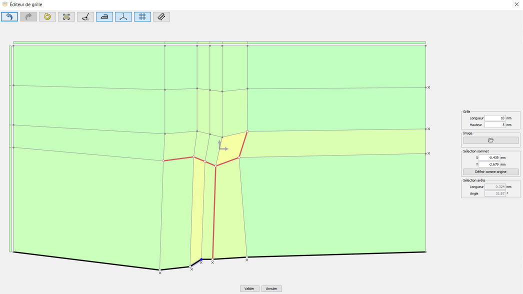
In order to modify the size of the defect, its shape, to add other defects or even to modify the shape of the grid, it is necessary to add lines (or segments). To add lines, position your mouse on a gray line or an already existing defect segment (red), and right click on it. Once you have created several nodes, you can add the segments (red) that will define the shape of your defect by clicking on the gray line generated between two nodes. This line will then turn red.
Note 1: You can also divide a red segment by clicking (left mouse button) on the line between the two vertices defining this segment. A new vertex will appear. All you have to do is double click on the unwanted segment, which will turn gray again.
Note 2: If you have chosen an outer or inner breaking notch, you can also modify the profile of the grid, which will generate the creation of a complex profile of your part for which the calculations will be carried out with the FE models of CIVA.
To remove a gray line, click on the “x” that appears just below (on the edge of the grid).
We hope that these elements will help you define your “FE interaction zone” defects.
You will find more information in the CIVA user manual.
Creation of a complex flaw with a locally complex background