
Display several scans in the 3D view
When simulating an inspection with several axis of variation (Mechanical Scanning, Increment, Electronic Scanning, Multiple shots, etc.), a C-Scan image is generated, and you may wish to display several scans in the 3D view. Then, you can see at a glance how one scan is affected by the change in the other axis.
It is possible to do that thanks to the “frozen scan” feature:
The configuration below involves a phased-array UT probe with a linear array. One electronic scanning is operated along the circumferential axis of the tubular specimen, while a mechanical increment is used along the axis. The simulation generates a Bscan image (Electronic Scanning vs. Time), a Dscan image (Increment vs. Time) and a Cscan image (Electronic Scanning vs. Increment):
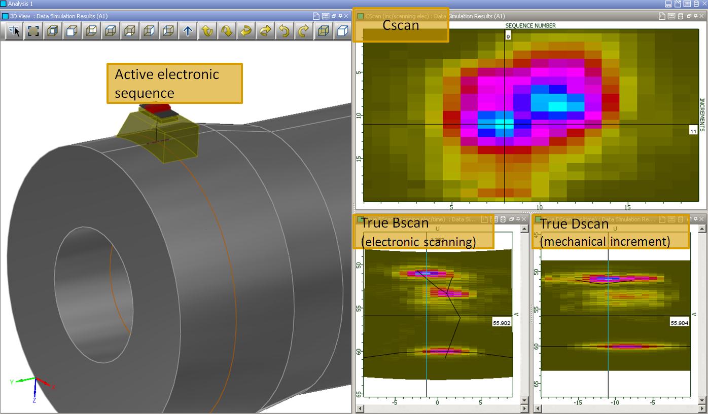
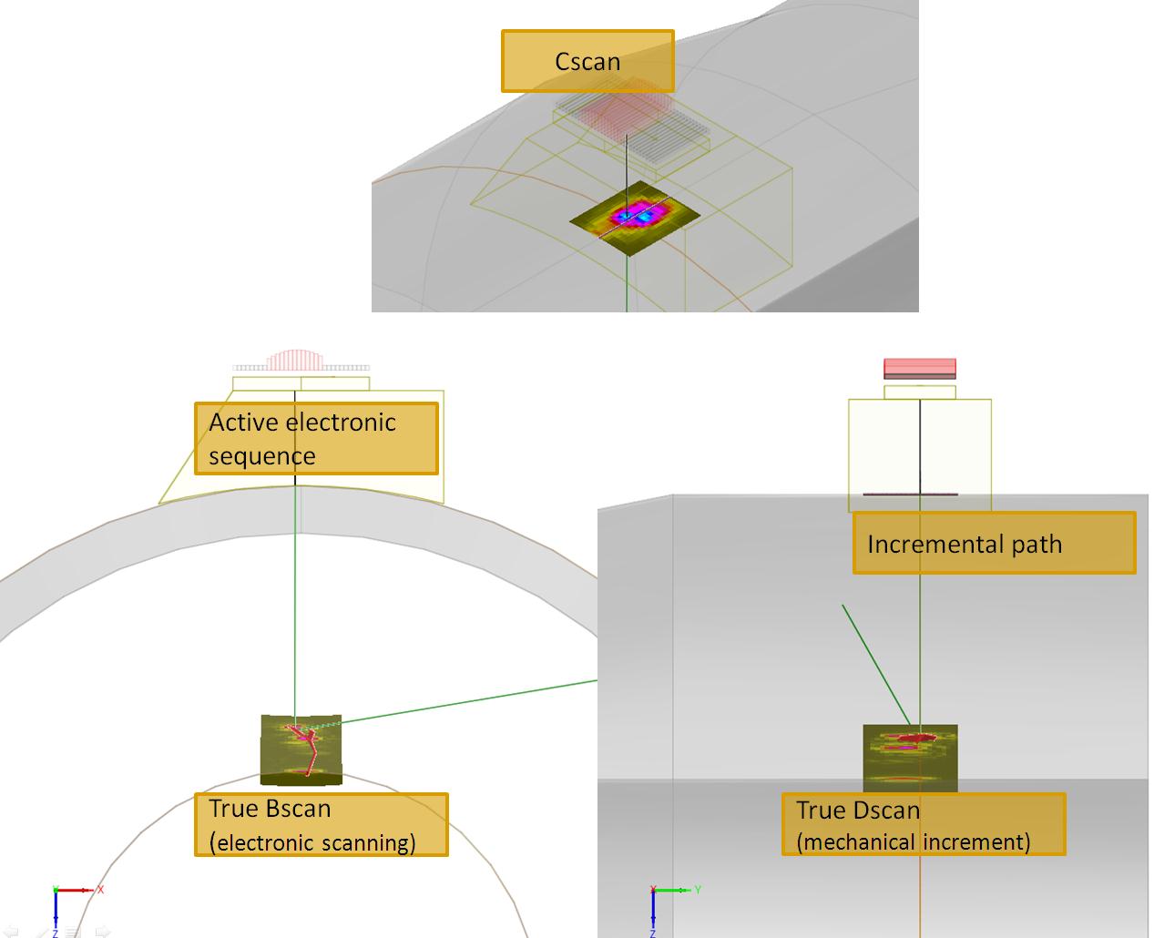
As an experienced user of CIVA, you already know that a simple drag and drop allows you to display an image in the 3D view. This superimposition of the true scans and the flaws helps the analysis of the different echoes:
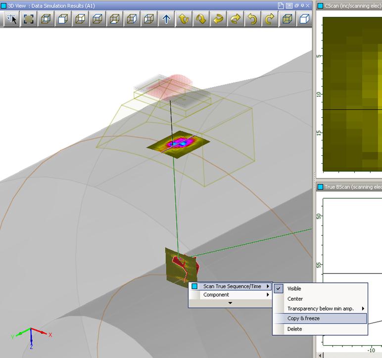
But it is also possible to display several Bscans (or Dscans) for several positions. To do this, right click on the first one displayed in the 3D view, then select “Copy & Freeze”. After that, when moving the cursor of the mechanical increment in the Cscan, a second image will appear. Think about changing the opacity of the scan for easier visualization (always from the “magical” right click contextual menu). Then, repeat the operation to obtain the desired number of cross-section views:
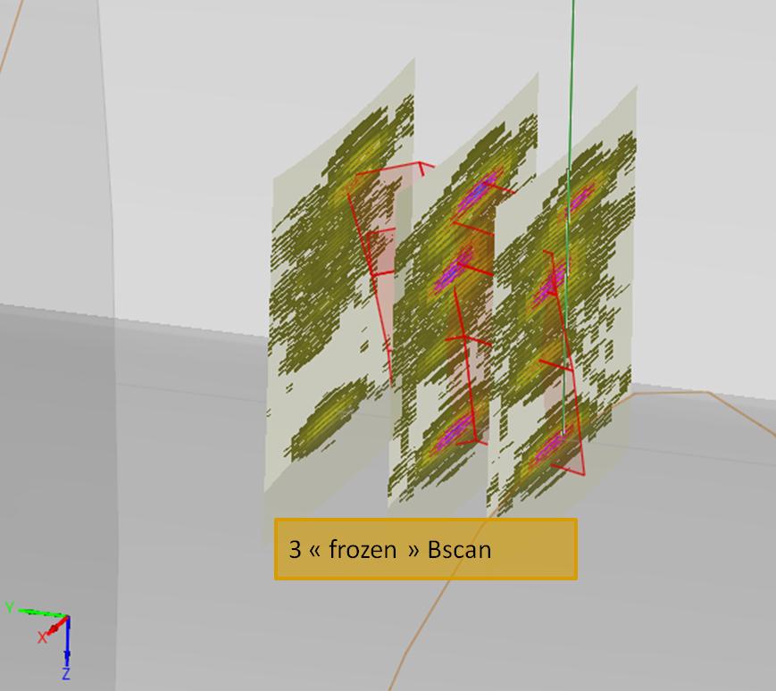
This advanced imaging capability facilitates a quick analysis of a given inspection, especially for complex flaw geometries, or when operating several series of shots with a PA probe.