
UT – Multiskip echoes: Experimental and simulation setup
Summary
Specimen
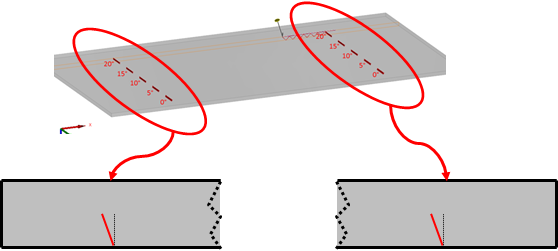
A specimen has been made especially for this study in order to have sufficient perspective to undergo multiple beam skips before reaching the notches. This is a flat mock-up of 5mm thickness containing 10 vertical backwall breaking notches . All the notches have the same height and extension (respectively 2mm et 20mm), but have different tilt angle : 0°, 5°, 10°, 15° and 20°.
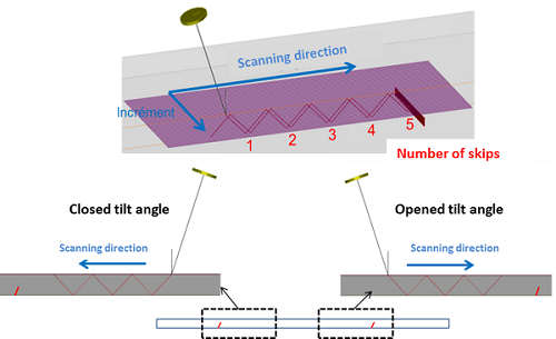
All notches are tilted in the same direction (see figure below) but they are inspected in opposite directions. According to the inspection direction, the configuration is named “closed tilt” or “opened tilt”. A clearer explanation is given in the following.
Probes
Conventional single probe, 5 MHz, Ø6.35 mm
The 5 MHz Ø6.35 mm diameter probe input signal was chosen so that experimental and simulated direct echoes of a Ø2 mm side drilled hole (SDH) located at 4 mm depth are in good agreement. The -12 dB probe bandwidth is 80%.
The incidence angle of the probe is chosen such that the desired wave type is generated in the specimen. The waterpath is 25 mm.
Phased array, 5 MHz
The phased array used for this study is a 5MHz linear probe constituted with 64 elements. The element pitch is 0.6 mm (0.5 mm element width + 0.1 mm space between elements), the element length (elevation) is 10 mm. The input signal was chosen such as experimental and simulated shear wave direct echoes of a Ø2 mm side drilled hole (SDH) located at 30 mm depth are in good agreement. The probe bandwidth at -6 dB is 70% and the central frequency is 4.3 MHz.
This probe was used in immersion with 50 mm water path and 18.59° incidence angle in order to generate T45° waves in the specimen. The active aperture of the probe is composed of 24 elements over the 64 from the probe. This number of active elements was chosen in order to generate naturally (i.e without use of delay laws) a focal point corresponding to a 3 skips path in the mock-up. Three delay laws were used to focus the ultrasonic beam at 5, 15 and 25 mm depth. They allow to focus the beam on the backwall after 1, 2 and 3 skips respectively.
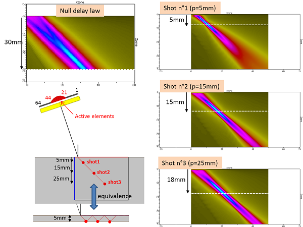
The figure above shows the 3 focal points and the associated beams calculated with CIVA 11. The beam simulated without use of delay law is also shown. The depth corresponding to the highest amplitude measured for each shot is indicated with a white dotted line on the cartographies.
simulation parameters
Simulations have been carried out with CIVA 11 and 3D calculation option was used for beam and defect responses. The input CIVA parameters used in simulation are given in the table below:
The input parameters used for simulation are reported below.
| L wave velocity | T wave velocity | Density | Attenuation |
| 5950 m/s | 3290 m/s | 7.8 g/cm³ | attenuation pour T waves : 0.014 dB/mm – power : 4 – frequency : 4.38 MHz |
Beam and defect response precision that were used are 3 and 3.
All simulations were performed with the “Kirchhoff + GTD” model available in CIVA 11.
experimental measurements
Experimental acquisitions were performed with equipment composed of a mechanical bench allowing C-scan acquisition and an electronic phased array acquisition system MultiX 64 controlled with the Multi2000 V6.7.32 software. An inspection procedure was followed to minimize sources of uncertainty. The global uncertainties associated with mechanical parameters, machined defects, and material homogeneity was assessed by verifying the reproducibility of the results. The experimental data interval of confidence has been estimated to be +/-2 dB (1dB due to the uncertainty of the measurement on the calibration defect and 1 dB due to the uncertainty of the measurement relatively to the reference).
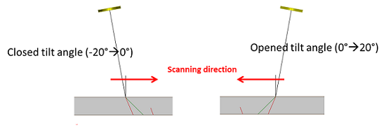
C-scan acquisitions were performed in the two scanning directions in order to detect the notches according the two possible tilt angles: closed tilt (tilt from -20° to 0°) and opened tilt (from 0° and 20°).
Calibration
The reference in amplitude is the T45° or the L45° (depending on the incidence angle of the probe) echo of a Ø2 mm SDH located at 5 mm depth for results obtained with the single probe.
Results obtained with the phased array probe are calibrated with maximal amplitude of a Ø2 mm SDH located at 30 mm depth and detected with T45° with no use of a delay law.
The steel of the mock-up containing the Ø2mm SDH (located between 5mm and 60mm depth with 5mm step) is not exactly the same as the one of the notches specimen. In order to evaluate the similitude between both, L and T wave velocities and attenuation were measured. Wave velocities were found to be different: the mock-up with notches has VL : 5950 m/s ; VT : 3290 m/s while the SDH specimen has VL : 5820 m/s ; VT : 3190 m/s. Furthermore, contrary to the “multi-skip” mock-up (i.e. notch specimen), the calibration specimen does not have any attenuation for shear waves. This difference between the steels is taken into account in CIVA. During the calibration, the probe incidence angle was adapted such as it generates ultrasonic beam identical in both parts.
Continue to Results for the 5 MHz single element transducer generating T45 waves