
UT – Corner echoes with SV mode: Conclusion and phenomena explication
Summary
CONCLUSION
There is a good agreement between experimental and simulated results on SV corner echoes when the notch is higher than the wavelength. In that case, the largest difference hardly exceeds 2 dB.
The largest discrepancies can be observed when the noches are smaller than the wavelength or when their height is close to it.
Further studies will continue on this topic.
PHenomena explication
It is observed that the difference between simulation and experiments increases when using a divergent probe and when the ratio of the notch size and the wavelength decreases. Several hypotheses can be proposed to explain these differences:
-
The “small defect” limitation of the Kirchhoff interaction model
-
Beam modelization limits
-
Critical contributions, or creeping waves, in particular for divergent beams
-
Echoes split and shift for large incidence
The “small defect” limitation of the Kirchhoff interaction model
In some cases, like for the contact probe of Ø6.35 mm diameter functioning at 2.25 MHz or immersion probes functioning at 2.25 MHz, discrepancies can be noticed, in particular for small defects. Some of these differences can be explained by the limits of the interaction model.
Indeed, the Kirchhoff beam-defect interaction model was developed for high frequency specular reflections. This implies that the defects radius (here, the half-height of the notch) should be larger than the wavelength and that the associated notch edges diffraction contributions are not simulated. The validity of the model is assured according an usual criteria based on the product of the wavenumber (k = 2*π/λ) with the defect radius (a): k.a>>1.
At 2 MHz, with a phase velocity in steel of 5800 m/s for P waves, the wavenumber k is 2.2 mm^-1 and the notch height must be larger than 0.9 mm. This explains why simulation is less accurate for notches of 0.5 mm or 1 mm high with semi-analytical models.
Update: The small defect limitation of the Kirchhoff interaction model can be bypassed in CIVA thanks to the Transient Finite Element Model (TFEM) available since CIVA 2020. The TFEM does not suffer from this limitation and allows simulation of all physical interaction phenomena between the beam and defect, inclusing creeping and Rayleigh waves.
Furthermore, it has been shown that the probe central frequency is not the only parameter that influences the Kirchhoff limitation, the bandwidth also has an influence. This last one is not studied in this document because all the probes that have been used have a bandwidth of almost 60%.
Beam modelization limits
Contrary to experimental echodynamic curves, the ones simulated on SDHs located at different depths are sometimes asymmetric. Moreover, the amplitudes may be also under-estimated. This phenomenon is observed when using immersion probes working at 2.25 MHz:
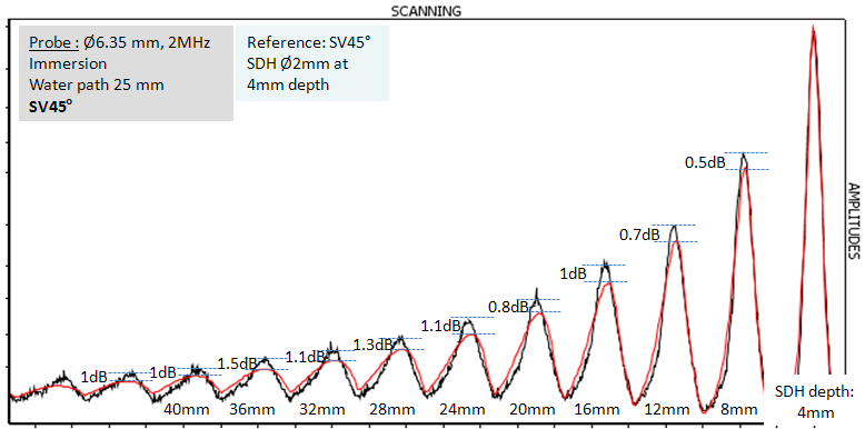
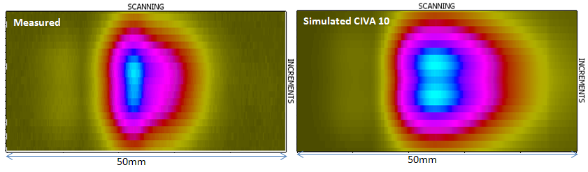
This phenomenon appears when inspecting high notches (for small notches, others phenomena can appear too). The figures below correspond to the experimental and simulated C-scans of the corner echo obtained with the 15 mm high notch. The comparison shows the asymmetric response of the notch: the experimental echo is less “spread” than the simulated one. The left side is correctly estimated while the echoes are spread on the right side of the Cscans below (for immersion probes of 2.25 MHz).
The differences observed on the echodynamic curves associated with the SDH and the notches can be due to a beam modelization problem. Indeed, the differences between experimental and simulated corner echoes could come from the hypothesis done in order to simplify the field description in the defect response module (with the plane wave approximation model). The wavefronts are supposed to be locally planar near the notch sampling point. However, the smaller is the probe, the less the hypothesis is verified. It is also the case when the flaw is in the near or very far field of the probe.
Performing a calibration at a different depth could limit the difference in amplitude but would not eliminate the results form inaccuracy.
Update: The Full Beam model available in the latest versions of CIVA does not make the assumption that wavefronts are planar near the defect as for the planar wave approximation model. Simulations with the Full beam model should then improve the beam prediction in these configurations.
Critical contributions, or creeping waves, in particular for divergent beams
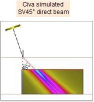
These phenomena are caused by the presence of waves in the beam arriving on the specimen backwall and/or the notch surface at incidences larger than the critical incidence. This can lead to the generation of surface waves. Note that the refraction angle for SV waves corresponding to the critical incidence angle in steel is 33° on the backwall and 57° on a vertical notch. The creeping and the head waves contributions can also explain the differences observed on the echodynamic curves because they bring additional contributions to the corner echo.
This phenomenon could explain a part of the observed differences with the immersion probe of Ø6.35 mm functioning at 2.25 MHz.
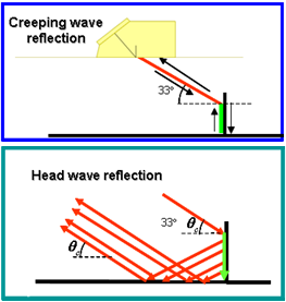
The image above illustrates the contribution of the creeping and head waves to the corner echo. It corresponds to a SV45 configuration with a steel planar specimen for which the critical angle is 33°, the creeping wave are in green. CIVA 10.1 calculates only the creeping waves on the backwall (left top), it does not model creeping waves on the entry surface or on the notch which explains the difference between simulation and experiments. The modelisation of such phenomena is in progress. Some of these contributions may be available in a next version of CIVA. Note that, these contributions are already available in the CIVA-Athena2D module.
Update : In CIVA 2021, plane wave approximation and Full beam model for beam/defect interaction still do not allow simulation of the creeping wave on the notch. However, since CIVA 2020, the Transient Finite Element Model allows to consider all the phenomena that may occur during beam/defect interaction inclusing creeping wave phenomenon. This explains why simulations with TFEM show good agreement with experiment.
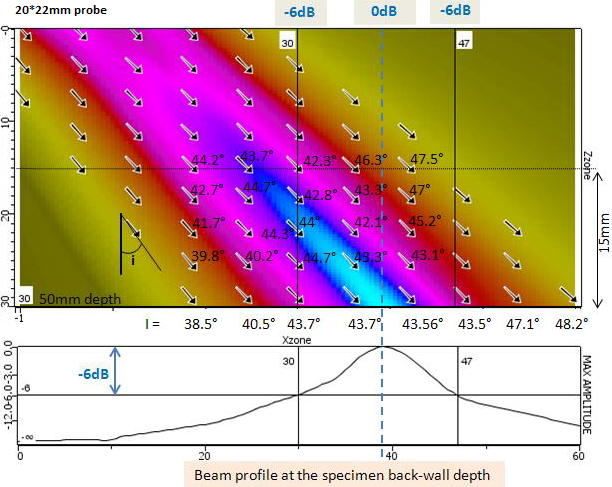
The simulation of the refracted field in the specimen with the SV45 contact probe of dimensions 22 mm x 20 mm, at 2 MHz is illustrated below.
On the cartography, the local directions of the field at each point of the calculation zone are displayed: they are represented with small arrows indicating the orientation of the beam at the corresponding point.
The probe’s beam is not divergent around the notch thanks to its dimensions and due to the notches depth (50 mm) which is close to the one where the maximal beam amplitude is measured. In the “main” width of the beam (delimited with the -6 dB lines), the wavefronts are planar and oriented according a propagation direction of 43.5°. There are no critical rays in this part of the beam and critical phenomena on the backwall (creeping and head waves) have no effect.
Depending on the notch position relatively to the probe, the notch location in the beam varies as shown on the following figure. Therefore, the incidence angles on the notch surface vary too. For a fixed probe position, these angles correspond to the ones illustrated along a vertical line on the following figure.
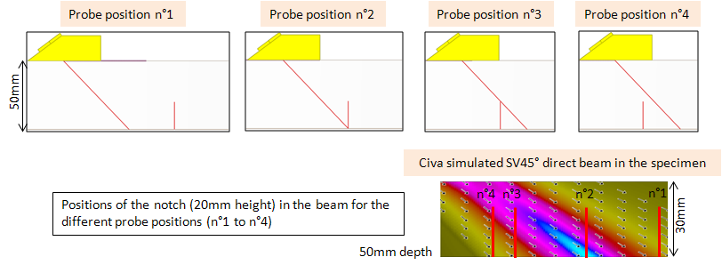
It can be seen that the rays arrive on the defect with an incidence angle different from the critical incidence (the critical incidence angles are around 57° on a vertical notch) and therefore, there is no critical phenomenon on the notch surface.
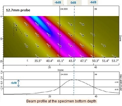
At the backwall depth, the beam radiated with a probe of Ø12.7 mm diameter functioning at 2.25 MHz, is oriented, at -6 dB, between 41° and 50°. The critical contributions can be neglected here too.
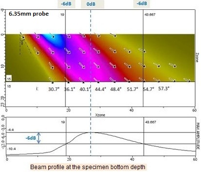
With the probe of Ø6.35 mm diameter at 2.25 MHz, the beam is more divergent. The beam profile on the specimen backwall, between the -6 dB lines, contains geometrical rays oriented between 36° and 55°. However, the beam is divergent. Therfore, weak critical incident rays (33° on the backwall and 57° on a vertical notch) can be observed close to this part of the -6 dB beam.
When the probe of 6.35 mm functioning at 2.25 MHz is located at favorable positions, some incident rays arrive on the notch surface with critical angles because of the great divergence of the beam. This could contribute to the differences observed between the experimental and simulated echodynamic curves. However, these critical contributions are very weak (the critical rays on the backwall or on the notch belong to a part of the beam with low amplitude) relatively to the one of the SV wave which is reflected twice (classical corner echo). This is especially true for the largest defects. For small flaws, the classical corner echo has a low amplitude; then, its simulated amplitude decreases of 11 dB when changing the height from 4 mm to 1 mm. Therefore, the relative contribution of creeping and head waves may have a larger effect on the global echo. However, in this configuration, the contributions due to critical phenomena are weak. It is difficult to separate the effects due to the beam modelization from the ones due to the critical contributions. Actually, with the smallest notches, it has been observed, with this probe, simultaneous effects of the frequency vs notch height, the beam modelization and the (weak) critical contributions. these three effects can not be separated.
The contributions associated with critical phenomena are very weak for SV45 corner echoes whereas they are more important for SV55, SV60 and SV65 because the critical rays are generated from incident rays of larger amplitude (around the probe axis).
Note that these phenomena may generate two different effects:
-
The generation of creeping and head waves for critical incidence angles on the notch or on the backwall specimen. These waves bring additional contributions to the corner echo and some of them are not simulated by CIVA 10 (Update : they still are not simulated in CIVA 2021 with plane wave approximation and Full beam model for beam/defect interfaction but they are accounted for in the TFEM model available since CIVA 2020). These contributions strongly depend on the notch size and on the frequency. The phenomena associated with these creeping and head waves have a strong influence on corner echoes amplitude especially for small notches.
-
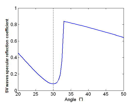
The speedy variation of the reflection coefficient relatively to the incidence angle which, around the critical angle, affects the reflected bulk waves on the specimen backwall and the notch. Indeed, the module of this coefficient is almost null below the critical angle, it is maximal above the critical angle. This coefficient runs the notch reflectivity which is strongly dependent on the real incidence angle on the notch (especially around the critical angle). It also affects the corner echo amplitude.
The coefficient variations may lead to effects even at angles far from the critical one (57°). For instance, because of these variations, echoes splitting may happen for some inspection modes. CIVA only considers average incidence for each point of the notch surface. This approximation may be too restrictive compared to a taking into account all the incident rays arriving on this point.
The combination of both previous effects may explicate the observed differences between experimental and CIVA echodynamic curves especially for divergent probes. These effects may appear for SV55 or SV60 refraction angles which are close to the critical incidence on the notch (SV57), they also appear for SV65 angles.
Since the interaction phenomena are very complex and depend on various parameters (SV wave refraction angle, notch height, beam divergence (i.e. probe aperture and central frequency), it is not possible, for the SV50°-SV60° angles close to the critical angle, to provide precise limits of the validity domain in terms of k.a for instance. For T45° the critical phenomena are more negligible, what allows sill reasoning with k.a limitation.
Echoes split and shift for large incidence
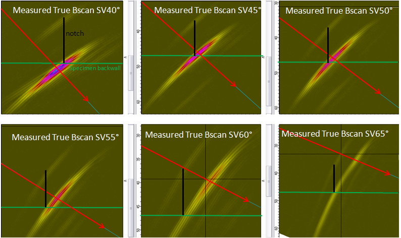
For SV waves with large incidence angles, it can be seen on both experimental and simulated results that the corner echoes are shifted from the notch edge, some are even split.
Corner echoes associated with bulk waves are, a priori, predominant in amplitude. The following explanations consider that no surface wave is propagating. The corner echo is essentially a specular phenomenon (especially for high notches) because of the bulk waves reflections on the notch and on the specimen backwall. Therefore, the explanations will be based on geometrical considerations.
For a 45° beam and for a scanning position where the focal axis of the SV refracted waves crosses the bottom of the notch, the direct field on the notch and the reflected field on the backwall are both maximal at the bottom of the notch. Because the corner echo is theoretically proportional to these direct and backwall reflected contributions, this echo is maximal at the bottom of the notch where the focal axis matches the notch.
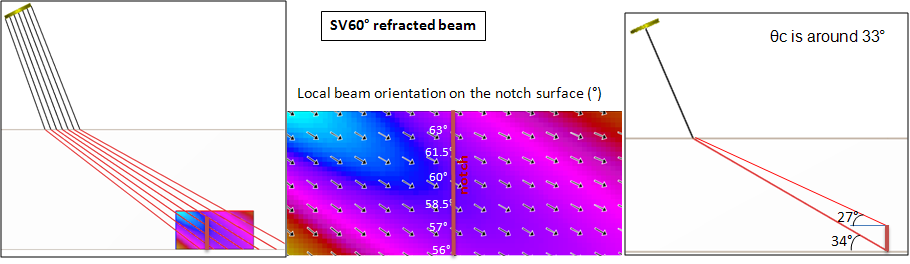
For a 60° beam (figure below), it can be seen that the refraction angles of the rays contained in the beam vary along the height of the notch between 56° (bottom of the notch) and 63° (top of the notch). Thus, the corresponding incidence angles on the notch surface vary between 27° and 34°. These angles are close to the critical angle ( θ = 33°) and thus correspond to a region of strong fluctuations of the Kirchhoff diffraction coefficient used to model echoes corner.
For instance, consider the 2 probe positions, “a” and “b”, illustrated below.
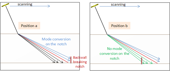
At position “a”, the beam intercepts the notch with incidences smaller than the critical one (blue rays in the figure). Mode conversions occur at the notch surface but the contribution of that portion of the beam to the SV corner echo is low (cf. Kirchhoff diffraction coefficient for angles lower than 33°).
At position “b” position, the beam reaches the notch with incidences larger than the critical one (green rays). For such incidences, SV wave reflection on the notch is very important (see Kirchhoff diffraction coefficient for angles larger than 33°) and especially more important that when the central ray of the beam reaches the defect root. Thus, in SV60° configuration, the maximum amplitude of the SV corner echo is obtained at scanning positions for which the SV focal axis intercepts the specimen backwall on the right of the bottom of the notch (position “b”). The position where the highest amplitude is measured is shifted relatively to the notch.
The same explanation may explain the division of the corner echo into two contributions. This phenomenon is due to the incidence angles variations in the rays contained in the refracted beam (variations dependent on the SV refraction angle and to their effect on the interaction with the notch. This corner echo division for SV60° is also reproduced with CIVA.
The following experimental B-scan allows the visualization of the split and the shift of the response when using an immersion probe of Ø12.7 mm at 2.25 MHz with a water path of 50 mm.
Back to Corner Echoes with SV mode
Back to Corner Echoes