
UT – SDH: Side Drilled Holes at different depths and Immersion probes
Summary
- Configuration
- RESULTS
- mono-ElEment immersion probe 2.25 MHz, Ø19 mm
- mono-ElEment immersion probe 2.25 MHZ, Ø12.7 MM
- MONO-ELEMENT IMMERSION probe 2.25 MHZ, Ø6.35 MM
- MONO-ELEMENT IMMERSION probe 2.4 MHZ, Ø20 MM
- MONO-ELEMENT IMMERSION probes 4.5 MHZ, Ø12.7 MM
- MONOELEMENT IMMERSION probe 4.7 MHZ, Ø6.35 MM
- Conclusion
Global overview:
| Immersion probes | 2.25 MHz Ø19 mm | 2.25 MHz Ø12.7 mm | 2.25 MHz Ø6.35 mm | 2.4 MHz Ø20 mm | 4.5 MHz Ø12.7 mm | 4.7 MHz Ø6.35 mm |
| P0° | Done | Done | Done | Done | ||
| P45° | Done | Done | ||||
| P60° | Done | Done | ||||
| SV45° | Done | Done | Done | Done | ||
| SV50° | Done | Done | ||||
| SV55° | Done | Done | ||||
| SV60° | Done | Done |
Configuration
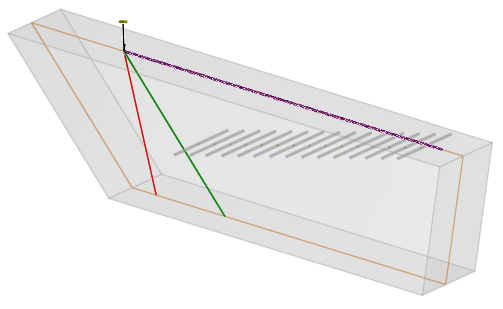
This validation experiment deals with Ø2 mm SDH at different depths. The measurements are performed upon a planar steel block containing Ø2 mm SDH from 4 to 60 mm depth with 4 mm steps. As a reminder, the steel parameters are: density 7.9, P waves velocity: 5900 m/s and SV waves velocity: 3230 m/s. Since the SDH are inspected perpendicularly to their axis, the SOV interaction model is considered.
The following picture presents the mock-up that is used.
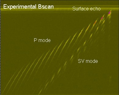
After scanning along the surface of the block, the following B-scan is displayed:
In this configuration, 6 different immersion probes have been used in Pulse Echo mode. All the probes are circular and have a flat surface (none focused):
| Frequency | Crystal | Mode | Water path | Calibration depth |
| 2.25 MHz | 19 mm | P0° | 50 mm | 20 mm |
| 12.7 mm | P0° | 50 mm | 12 mm | |
| 6.35 mm | SV45°, P0° | 20 mm | 12 mm (P0°-20mm) | |
| 2.4 MHz | 20 mm | SV45°, SV60°, P45°, P60°, P0° | 50 mm | 32 mm (SV45°) |
| 4.5 Mhz | 12.7 mm | SV45° à SV60° | 20 mm | 32 mm (SV45°) |
| 4.7 MHz | 6.35 mm | P et SV, de 45°à 60° | 25 mm | 4 mm (P45°) |
RESULTS
For each probe, the simulated P or/and SV beam radiated in the specimen and in the incidence plane is displayed for at least one configuration.
The superimposition of measured and simulated curves of maximal relative amplitude of the P and SV specular echoes of the SDH versus the SDH depths are presented in the next figures.
mono-ElEment immersion probe 2.25 MHz, Ø19 mm
For the Ø19 mm circular immersion probe at 2.25 MHz with 50 mm water path, the P0° mode is used for inspection. The input signal frequency is 2.25 MHz, with 60% bandwidth and 0° phase.
The acoustic focusing depth is 19 mm, deduced from the simulated beam as illustrated below:
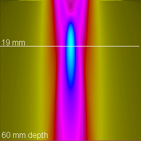
The results are calibrated versus the Ø2 mm SDH at 20 mm depth.
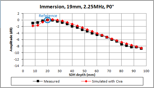
There is a good agreement between the results from the measurements and the results from CIVA software. The discrepancy is always less than 1 dB.
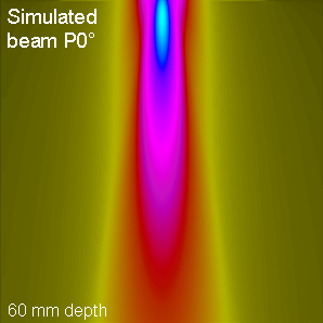
mono-ElEment immersion probe 2.25 MHZ, Ø12.7 MM
For the Ø12.7 mm circular immersion probe at 2.25 MHz with 50 mm water path, the P0° mode is used for inspection. The input signal frequency is 2.25 MHz, with 60% bandwidth and 0° phase.
The acoustic simulated beam is illustrated below.
The results are calibrated versus the Ø2 mm SDH at 12 mm depth.
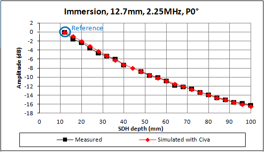
There is a good agreement between the results from the measurements and the results from CIVA software.
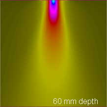
MONO-ELEMENT IMMERSION probe 2.25 MHZ, Ø6.35 MM
For the Ø6.35 mm circular immersion probe at 2.25 MHz, the P0° mode is used for inspection with 20 mm water path, and the SV45° with 20 mm water path. An experimental input signal (the SV45° specular echo of a Ø 3 mm and 45° tilted Flat Bottom Hole at 10 mm depth) is used for P0° waves. The input signal frequency is 2.25 MHz, with 64% bandwidth and 290° phase for the SV45° wave.
The acoustic simulated beam is illustrated below for the P0° mode.
The results are calibrated versus the Ø2 mm SDH at 8 mm depth.
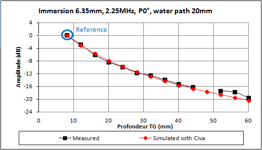
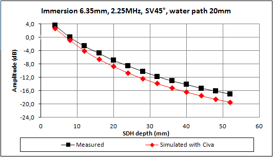
There is a good agreement between the results from the measurements and the results from CIVA software. The maximum discrepancy is 1 dB for P0° and 2 dB for SV45°.
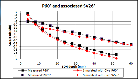
MONO-ELEMENT IMMERSION probe 2.4 MHZ, Ø20 MM
For the Ø20 mm circular immersion probe at 2.4 MHz with 20 mm water path, experiments are carried out with SV45°, SV60°, P45°, P60° and P0° modes. It can be noticed that for P45° and P60°, an associated SV beam radiates at 22° and 26° respectively. The input signal frequency is 2.4 MHz, with 53% bandwidth and 170° phase.
The acoustic focusing depth is 32 mm for the SV45° mode, deduced from the simulated beam as illustrated below.
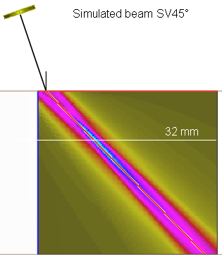
The results are calibrated versus the Ø2 mm SDH at 32 mm depth inspected in SV45° mode.
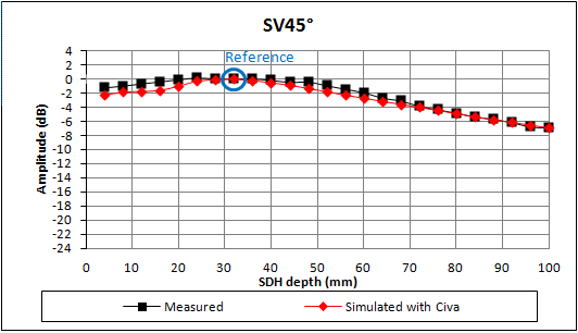
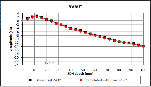
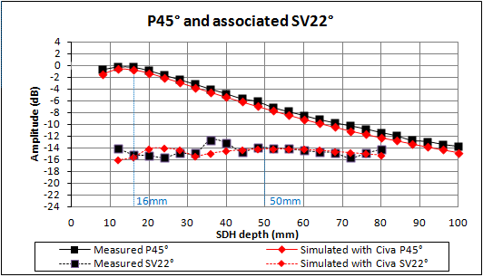
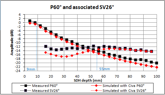
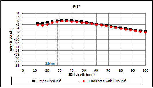
From the 5 previous figures, there is a good agreement between the results from the measurements and the results from CIVA software. It appears that the amplitude of the main echo is well estimated with less than 2 dB in the worst case for nearly all the studied configurations.
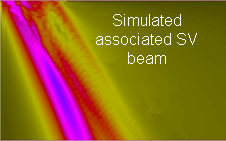
Just one case shows more discrepancy, it correponds to the SV26° mode associated with the P60° mode, which shows a discrepancy up to 4 dB in near field (less than 4 dB difference). It is due to a splitting in the SV beam at the water/steel interface, which is not observed experimentally. The SV beam splitting is due to limitations of the model. The strong variation of the transmission coefficient close to the critical angle splits the SV incident beam. Some waves are not considered, which reduces the amplitude of the SV simulated echo.
Split of the SV beam for a Ø12.7 mm circular contact probe generating P45° waves.
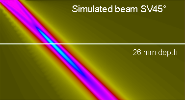
MONO-ELEMENT IMMERSION probes 4.5 MHZ, Ø12.7 MM
For the Ø12.7 mm circular immersion probe at 4.5 MHz with 20 mm water path, the SV45° to SV60° waves are used for inspection. The input signal frequency is 4.5 MHz, with 73% bandwidth and 270° phase.
The acoustic focusing depth is 26 mm for the SV45° mode, deduced from the simulated beam as illustrated below.
The results are calibrated versus the Ø2 mm SDH at 32 mm depth inspected in SV45° mode.
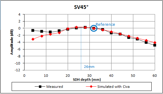
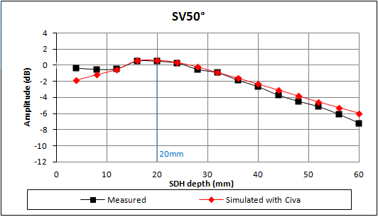
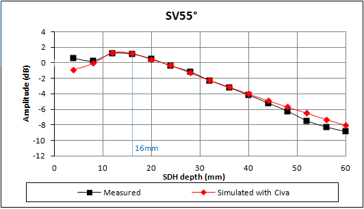
There is a good agreement between the results from the measurements and the results from CIVA software. It can just be noticed that CIVA underestimates the echo in the very near field of around 2 dB.
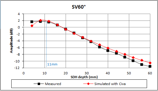
MONOELEMENT IMMERSION probe 4.7 MHZ, Ø6.35 MM
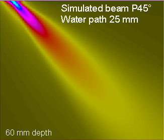
For the Ø6.35 mm circular immersion probe at 4.7 MHz, different waves are used for inspection (P and SV modes, from 45° to 60°). The water path is 25 mm for all cases except one where it is 10 mm. The input signal frequency is 4.7 MHz, with 56% bandwidth and 255° phase.
The acoustic simulated beam is illustrated below for the P45° mode with 25 mm water path.
The results are calibrated versus the Ø2 mm SDH at 4 mm depth inspected in P45° mode with 25 mm water path.
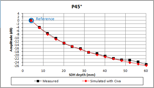
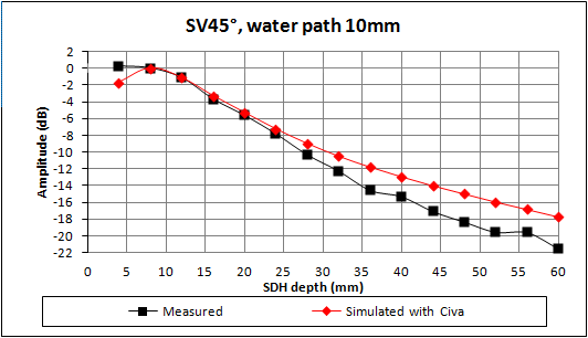
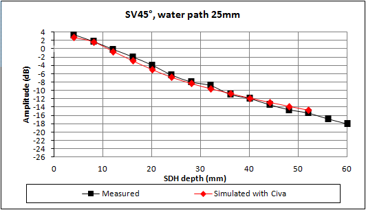
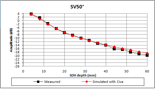
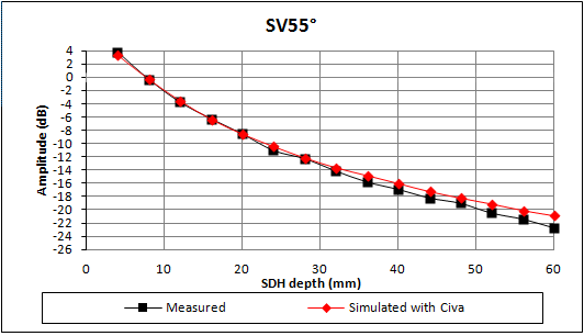
Whatever the incidence angle and the water path, the simulated results fit measurements with less than 2 dB discrepancy.
It can just be noticed with this crystal size that for the SV45° mode, the discrepancy tends to increase at larger depths, as it was already observed with the same crystal size at 2.25 Mhz.
Conclusion
Results show a good agreement with generally less than 2 dB difference for mono-element immersion probes.
The discrepancy may be a little higher in the near field. This is due to limitations of the model and is explained in details for rectangular contact probes.
Continue to Side drilled holes at different depths and contact probes
Back to Side drilled holes
Back to Calibration defects