
UT – Surface Echoes: Probe tilt variation
Summary
This study has been carried out with four immersion probes which characteristics are reported in the table below. The configurations are detailed thereafter for each probe.
| Ø Crystal (mm) | Mode | Frequency (MHz) | Bandwith (%) | Phase (°) |
|---|---|---|---|---|
| 12.7 | L, 0° to 10° | 5 | 65 | 220 |
| Linear (32 elts) | L, 0° to 10° | 10 | 55 | 290 |
| Matrix (9 elts) | L0° | 3.5 | 75 | 0 |
Probe Ø 12.7 mm, 5 MHz, incidence L0° to 10°
| Ø Crystal (mm) | Mode | Frequency (MHz) | Bandwith (%) | Phase (°) |
|---|---|---|---|---|
| 12.7 | L, 0° to 10° | 5 | 65 | 220 |
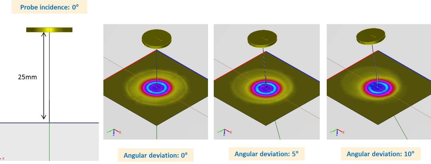
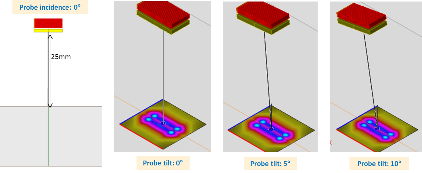
In this case, the surface echo has been measured for probe tilts from 0° to 10° and a water path of 25 mm. Examples of radiated fields in water for probe tilts from 0°, 5° and 10° are represented in the figure below, on which it can be seen that field amplitudes are comparable.
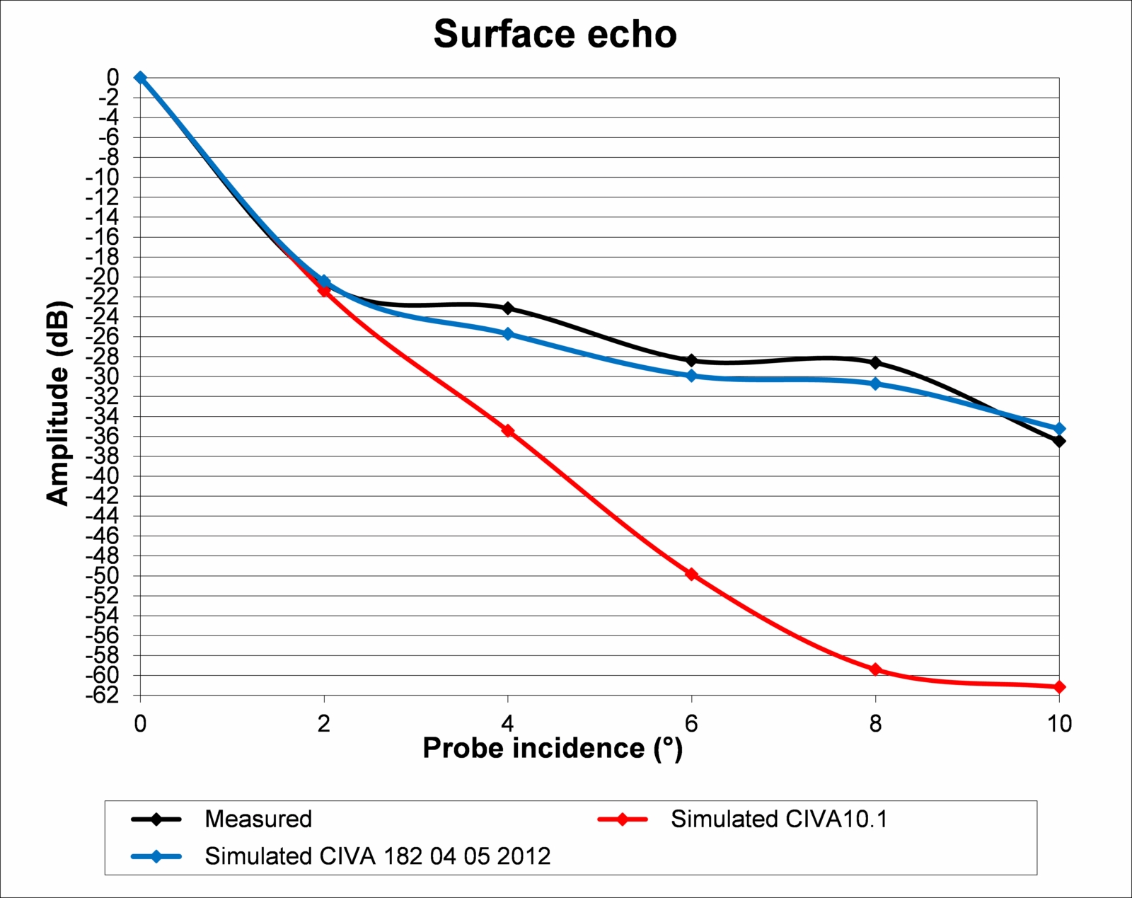
The results are calibrated with a surface echo measured at an incidence of 0°. The surface echo amplitudes obtained for several probe incidence angles with a water path of 25 mm are plotted here below in black for the measured results, in red for Kirchhoff model results and in blue for specular model results.
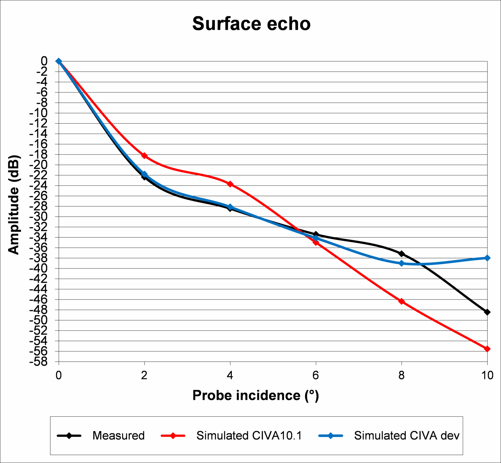
The specular model provides better results than the Kirchhoff model, with less than 2 dB difference compared to the measurements, except in the case of a probe incidence of 10° for which a gap of 12 dB is observed. In this case, the echo is very weak and has a complex shape (See the Ascans here below). For its part the Kirchhoff model gives worse results.
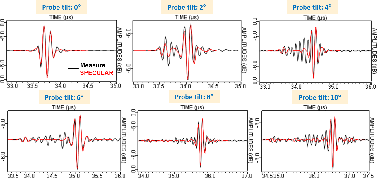
The measured and simulated Ascans with specular model are represented here below for six different incidence angles; the red curve corresponds to the specular model and the black one to measured results.
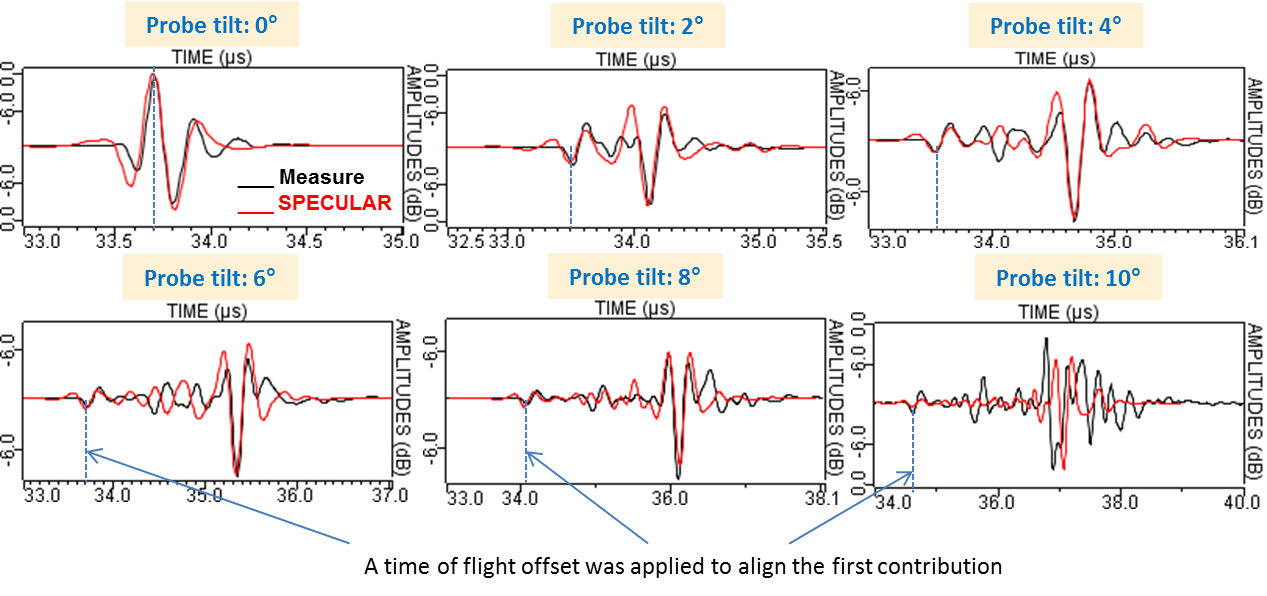
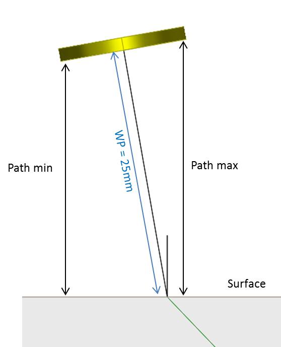
The signals simulated by the specular model are in good agreement with the measured results, except for the incidence of 10° for which the signal shape is very complex. From the beam steering of 16°, two clearly separated angular contributions appear. The times of flight of both contributions correspond to the paths of the normal rays of the specimen surface emitted by both probe extremities, as illustrated below.
However, between both contributions, echoes appear on experimental Ascans whereas they are not predicted by simulation. The effect of the displacement field uniformity hypothesis on the probe surface has to be studied, and can be used to interpret these results.
Linear probe, 10 MHZ, INCIDENCE L0°
| Ø Crystal (mm) | Mode | Frequency (MHz) | Bandwith (%) | Phase (°) |
|---|---|---|---|---|
| Linear (32 elts) | L, 0° to 10° | 10 | 55 | 290 |
The dimensions of this transducer are 6.55 mm x 5 mm.
The surface echo has been measured for probe tilts from 0° to 10° and a water path of 25 mm. Examples of radiated fields in water for probe tilts of 0°, 5° and 10° are represented on the figure below, on which it can be seen that field amplitudes are comparable.
The results are calibrated with a surface echo measured at an incidence of 0° and a null delay law. Surface echo amplitudes obtained for several probe incidence angles with a water path of 25 mm are plotted here below in black for the measured results, in red for Kirchhoff model results and in blue for specular model results.
Excellent results are obtained with the specular model. The Kirchhoff model underestimates the amplitudes up to 23 dB compared to measurements for angular probe deflection greater than 2°.
Measured and simulated Ascans with the specular model are represented here below for six different incidence angles; the red curve corresponds to the specular model and the black one to measured results.
The Ascans predicted by the specular model and measured results are quite similar. However, like previously, echoes appearing between contributions coming from both probe extremities are measured but not simulated. The origin of those contributions has to be studied.
Matrix probe, 3.5 MHz, L0°
| Ø Crystal (mm) | Mode | Frequency (MHz) | Bandwith (%) | Phase (°) |
|---|---|---|---|---|
| Matrix (9 elts) | L0° | 3.5 | 75 | 0 |
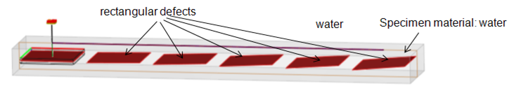
Measurements have been carried out by EADS with a 6mm x 6mm matrix probe on the specimen below:
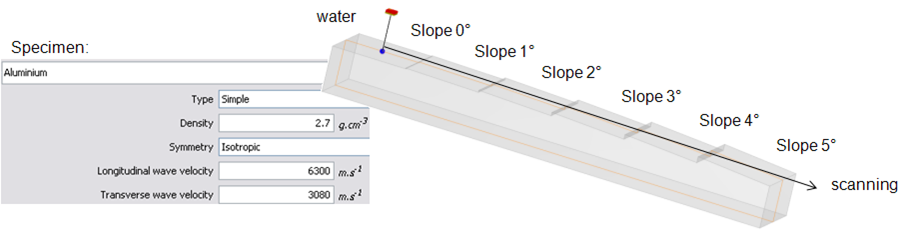
The different tilted surfaces have been modeled in CIVA by flat defects of the same dimensions and orientation as the surface steps, in a piece made of water, like this:
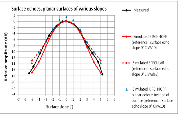
In the following graph, it is correctly predicted that the measured amplitude of the surface echo decreases with the surface tilt. A good agreement is also observed between surface echoe amplitudes and amplitudes of planar defect echoes simulating the surface, obtained with Kirchhoff model.
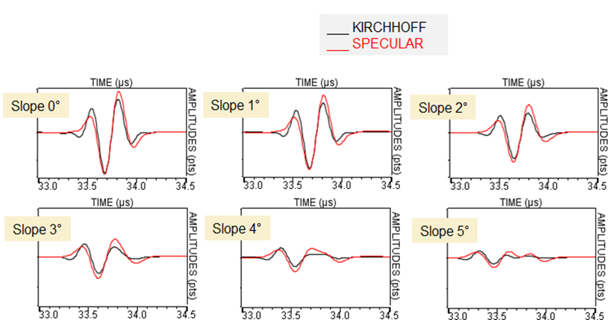
Ascan shapes for those surface echoes predicted with both models are quite similar:
Continue to Beam steering laws around L0°
Back to surface echoes
Back to geometrical echoes