
UT – SDH: Side Drilled Holes at different depths and Contact probes
Summary
- Configuration
- RESULTS
- mono-ElEment contact Probe 2.0 MHz, 20 x 22 mm, SV45°
- MONO-ELEMENT CONTACT probe 2.0 MHZ, 20 X 22 MM, SV60°
- MONO-ELEMENT CONTACT probe, 2.25 MHZ, Ø12.7 mm
- MONO-ELEMENT CONTACT probe, 2.25 MHZ, Ø6.35 MM
- MONO-ELEMENT CONTACT probe, 4.35 MHZ, Ø12.7 MM
- MONO-ELEMENT CONTACT probe, 4.8 MHZ, Ø6.35 MM
- MONO-ELEMENT CONTACT probe, 5.0 MHZ, Ø6.35 MM
- conclusion
Global overview:
| Contact probes | 2.0 MHz 20×22 mm | 2.0 MHz Ø12.7 mm | 2.25 MHz Ø12.7 mm | 2.25 MHZ Ø6.35 mm | 4.35 MHz Ø12.7 mm | 4.8 MHz Ø6.35 mm | 5.0 MHz Ø6.35 mm |
| P45° | Done | Done | |||||
| P60° | Done | ||||||
| SV45° | Done | Done | Done | Done | Done | ||
| SV60° | Done |
Configuration
Comparisons between measured and simulated data are also done with contact probes on the steel mock-up with Ø2 mm SDH. The measurements are performed upon a planar steel block containing Ø2 mm SDH from 4 to 60 mm depth with 4 mm steps. As a reminder, the steel parameters are: density 7.9, P waves velocity: 5900 m/s and SV waves velocity: 3230 m/s. Since the SDH are inspected perpendicularly to their axis, the SOV interaction model is considered.
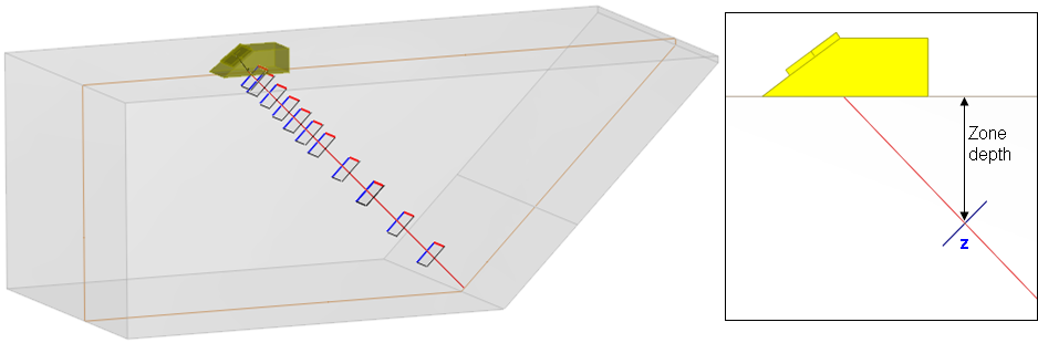
The following picture presents the mock-up that is used:
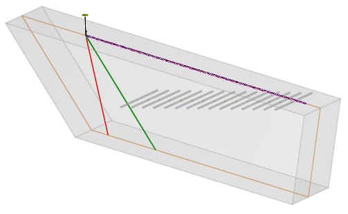
Different contact probes are used in Pulse Echo mode:
| Frequency | Crystal | Mode | Calibration depth |
| 2.0 MHz | 20×22 mm | SV45° | 52 mm |
| 20×22 mm | SV60° | 32 mm | |
| 12.7 mm | SV45° | 20 mm | |
| 2.25 MHz | 12.7 mm | P45° | 8 mm |
| 12.7 mm | P60° | 4 mm | |
| 6.35 mm | SV45° | 4 mm | |
| 4.35 MHz | 12.7 mm | SV45° | 36 mm |
| 4.8 MHz | 6.35 mm | SV45° | 8 mm |
| 5.0 MHz | 6.35 mm | P45° | 4 mm |
RESULTS
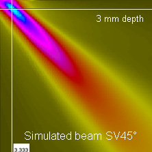
For each probe, the simulated P or/and SV beam radiated in the specimen and in the incidence plane is displayed for at least one configuration. For each probe, the calibration defect is the closest SDH to the focusing depth.
The superimposition of measured and simulated curves of maximal relative amplitude of the P and SV specular echoes of the SDH versus the SDH depths are presented as the next figures.
mono-ElEment contact Probe 2.0 MHz, 20 x 22 mm, SV45°
For the 20 x 22 mm rectangular SV45° contact probe at 2 MHz, the SV45° mode is used for inspection. The input signal frequency is 2.0 MHz, with 41% bandwidth and 75° phase.
The acoustic focusing depth is 53 mm, deduced from the simulated beam as illustrated below.
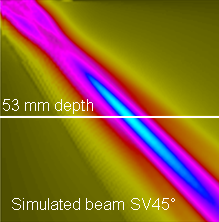
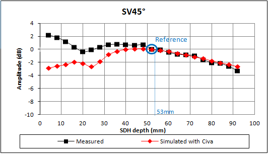
The results are calibrated versus the Ø 2 mm SDH at 52 mm depth.
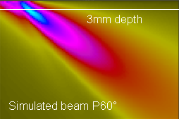
MONO-ELEMENT CONTACT probe 2.0 MHZ, 20 X 22 MM, SV60°
For the 20 x 22 mm rectangular SV45° contact probe at 2 MHz, the SV60° mode is used for inspection. The input signal frequency is 2.0 MHz, with 40% bandwidth and 0° phase.
The acoustic focusing depth is 32 mm, deduced from the simulated beam as illustrated below.
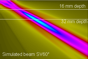
The results are calibrated versus the Ø2 mm SDH at 32 mm depth.
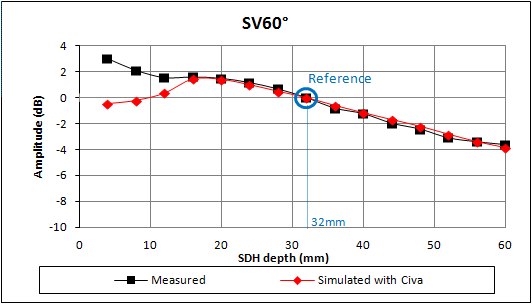
For both probes, the curves show a good agreement between simulated and measured results in the far field zone and less than 2 dB difference from the focal depth to the half of the focal depth.
The discrepancy is higher in the very near field.
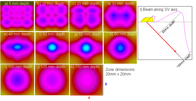
These figures show the interferences between the planar wave and the edge waves of the probe leading to interferences patterns observed in the computation zones at the lower depths (within the near field distance of the probe). These interferences give rise to a lower amplitude of the field. Therefore the measured responses of the flaws seem to be coherent with this field computation. However the defect response module is based on a simplification of the radiated field. This simplification is less valid in the near field so that this additional phenomenon may cause this discrepancy with the model.
MONO-ELEMENT CONTACT probe, 2.25 MHZ, Ø12.7 mm
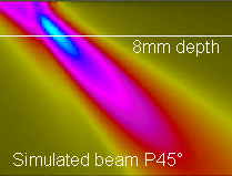
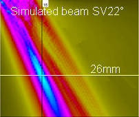
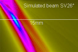
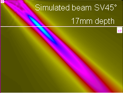
For the Ø12.7 mm circular contact probe at 2.25 MHz, the P45°, P60° and SV45° waves are used for inspection. The input signal frequency is 2.25 MHz, with 50% bandwidth and 280° phase for the P waves. The input signal is the inverse P45° experimental direct specular echo of a Ø3 mm FBH, tilted at 45° and located at 30 mm depth for the SV45° waves. P beams are associated with lower incidence SV beams: SV22° for P45° and SV26° for P60°.
The acoustic focusing depths are 8 mm, 26 mm, 3 mm, 15 mm and 17 mm respectively for the P45°, SV22°, P60°, SV26° and SV45° modes, deduced from the simulated beam as illustrated below.
 ;
; 
The results are calibrated versus the Ø2 mm DSH at 8 mm, 4 mm and 20 mm depth for respectively P45°, P60° and SV45° waves.
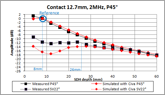
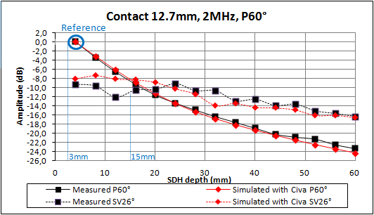
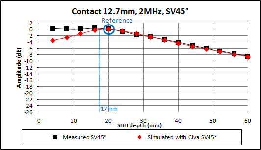
The amplitudes of the echoes from P waves are well predicted, the maximum discrepancy being less than 2 dB. The amplitudes of the echoes from SV waves show higher discrepancies in the near field zone (less than 5 dB) but are often correctly estimated.
MONO-ELEMENT CONTACT probe, 2.25 MHZ, Ø6.35 MM
For the Ø6.35 mm circular contact probe at 2.25 MHz, the SV45° mode is used for inspection. The input signal frequency is 2.25 MHz, with 44% bandwidth and 147° phase.
The acoustic focusing depth is 3 mm, deduced from the simulated beam as illustrated below.
The results are calibrated versus the Ø2 mm SDH at 4 mm depth.
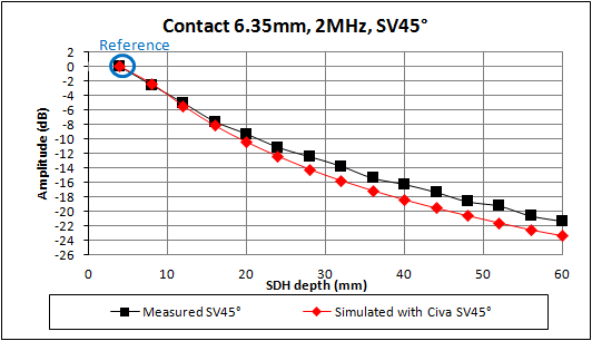
The discrepancy between simulated and measured results increases with the SDH depths but always less than 3 dB, there is a good agreement.
MONO-ELEMENT CONTACT probe, 4.35 MHZ, Ø12.7 MM
For the Ø12.7 mm circular contact probe at 4.35 MHz, the SV45° mode is used for inspection. The input signal frequency is 4.3 MHz, with 71% bandwidth and 330° phase.
The acoustic focusing depth is 31 mm, deduced from the simulated beam as illustrated below.
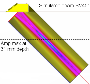
The results are calibrated versue the Ø2 mm SDH at 36 mm depth.
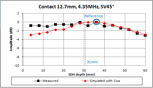
It can be observed that the simulated amplitudes are smoother than the experimental amplitudes which highlight probably a slight discrepancy in the measurements. There is an overall good agreement, the maximum discrepancy is less than 2 dB, and from 20 mm to 60 mm depth, the discrepancy is always less than 1 dB.
MONO-ELEMENT CONTACT probe, 4.8 MHZ, Ø6.35 MM
For the Ø6.35 mm circular contact probe at 4.8 MHz, the SV45° mode is used for inspection. The input signal frequency is 4.8 MHz, with 45% bandwidth and 90° phase.
The acoustic focusing depth is 8 mm, deduced from the simulated beam as illustrated below.
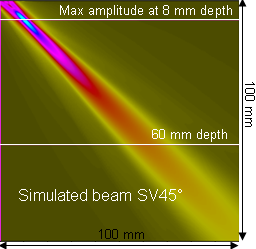
The results are calibrated versus the Ø2 mm SDH at 8 mm depth.
The discrepancy is always less than 2 dB, there is an overall good agreement.
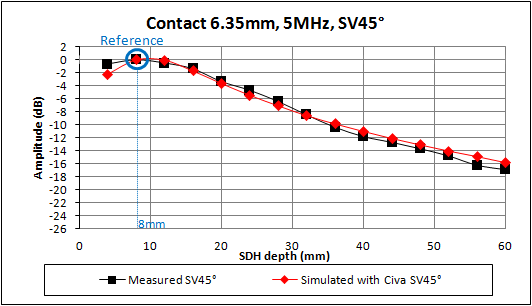
MONO-ELEMENT CONTACT probe, 5.0 MHZ, Ø6.35 MM
For the Ø6.35 mm circular contact probe at 5 MHz, the P45° mode is used for inspection. The input signal is the inverse P45° experimental direct specular echo of a Ø 2 mm SDH at 8 mm depth.
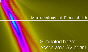
The acoustic focusing depths are 3 mm and 12 mm for respectively the P45° and SV22° modes, deduced from the simulated beam as illustrated below.
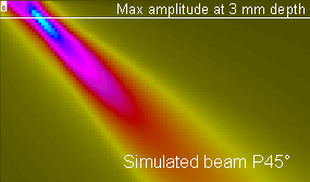
The results are calibrated versus the Ø2 mm SDH at 4 mm depth.
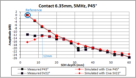
The discrepancy is less than 2 dB for the 45° beam in the far field, there is an overall good agreement. In the near field zone, the SV beam associated with the P45° beam shows a discrepancy between 2 and 4 dB, the simulation underestimates the echo.
At 32 mm and 36 mm depth, both SV22° and P45° experimental echoes are a little under-estimated since the SDH are damaged by rust. This block is no longer used for experimental validation.
conclusion
Results show a good agreement with generally less than 2 dB difference in this case of SDH and mono-element contact probes. For a given probe, it can also be concluded that an SDH echo obtained for a given mode, can be used as calibration echo for all the other modes generated by the same probe with different settings.
The hypothesis of non-distorted waveform on flaw, considered by CIVA models, is generally valid in the far field zone or the focal zone but less in the near field zone, which leads to some discrepancies (less than 5 dB) when considering flaws in the near or the very near field (from 0 to 50% of the focusing depth).
Continue to Side drilled holes at different depths and phased-array probes
Back to Side drilled holes
Back to Calibration defects