In the ET module, two types of computation are available: beam computation and inspection simulation.
Field Computation
The capabilities of the field computation include:
- Planar (potentially multilayer) and Cylindrical component geometries
- Ferromagnetic or non-ferromagnetic materials
- Surface coil (air core or cylindrical ferrite core), bobbin coil configuration
- Variable operational frequency
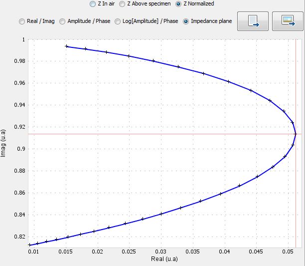
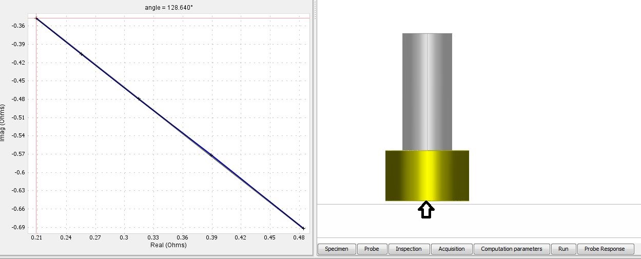
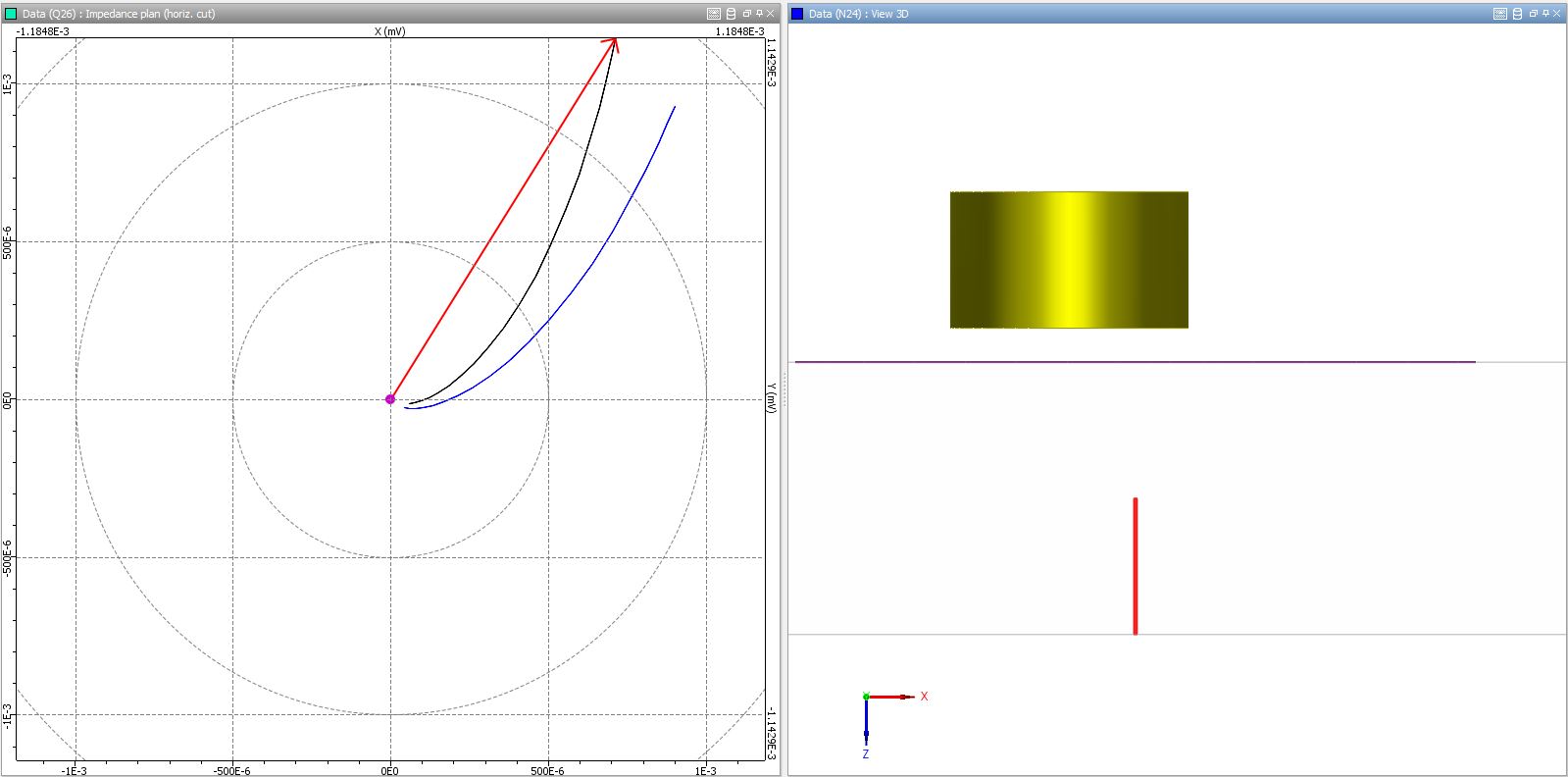
- Computes electromagnetic fields, impedance diagram and lift-off signal
Examples of simulations
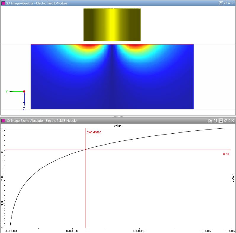
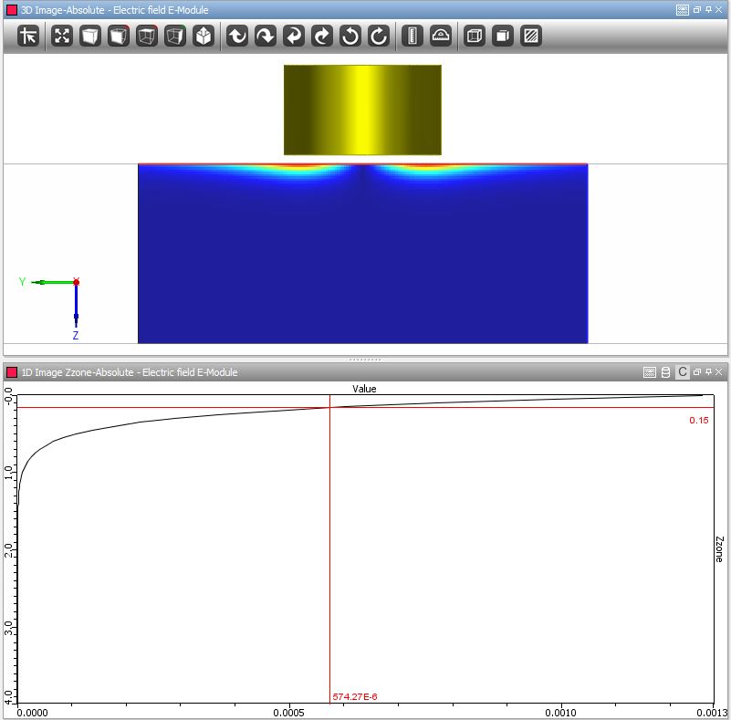
The ET field computation module of CIVA Education can help you make visible what is a bit hidden and looks complex in this electromagnetic technique:
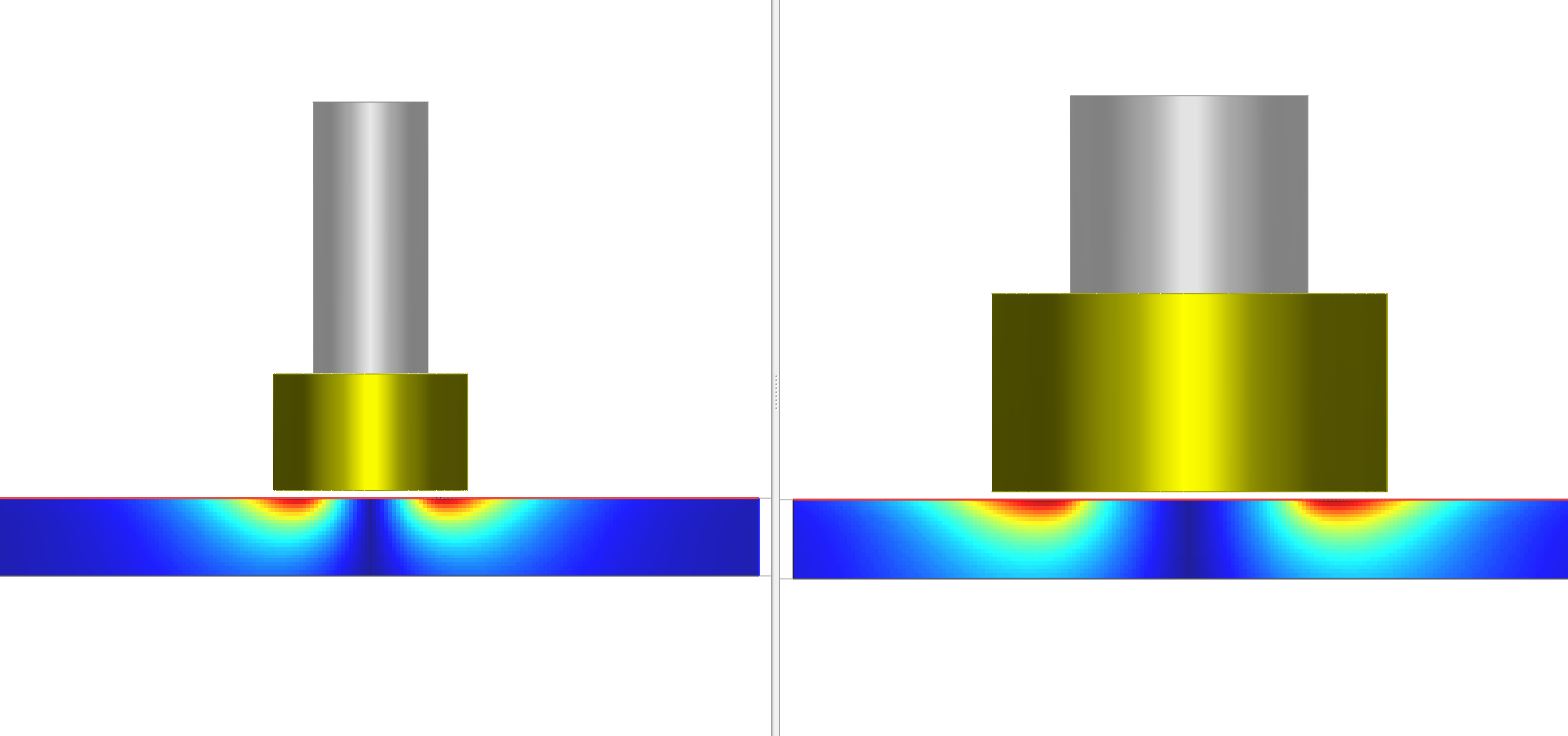
- Illustrate the Eddy Current penetration depth and observe the impact of the frequency, the material but also the sensor size on the actual penetration.
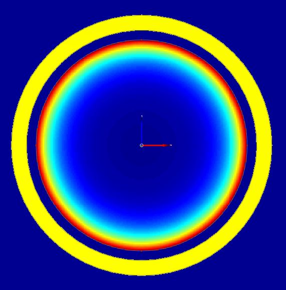
- Visualize the action zone of an ET sensor.
- Observe Eddy Current distribution in a tube or a solid bar.
- Understand and interpret Impedance diagram.
- See the influence of a ferrite core on the field induced by an ET sensor.
- Explain the lift-off signal and its potential consequence on calibration procedure.
- And many other ideas...
Inspection simulation
The features available in the ET inspection simulation module are:
- Planar and Cylindrical component geometries
- Conductive non-ferromagnetic materials
- Surface coil (air core or cylindrical ferrite core), bobbin coil configuration
- Simulation of cylindrical hole in tubes or rectangular notch in planar component
- Variable operational frequency
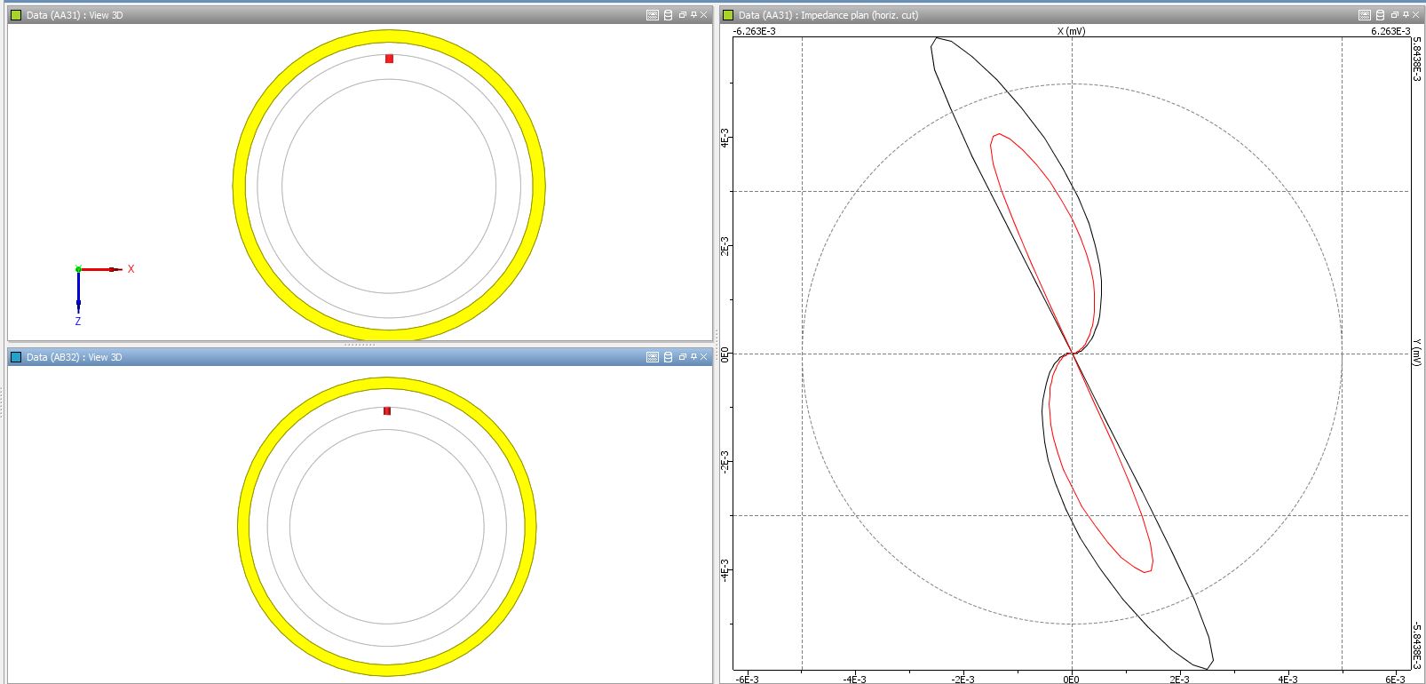
- Absolute or Differential mode
Examples of simulations
The ET inspection simulation module of CIVA Education can reproduce typical Eddy Current signals and help you in the following context:
- Explain the main acquisition modes: separated or common functions, absolute or differential measurement.
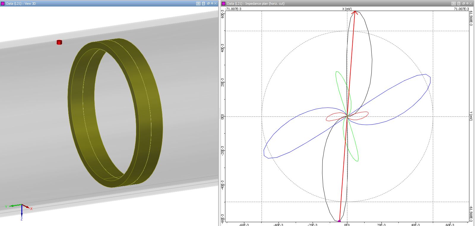
- Simulate classical tube inspection setup and explain the use of the phase angle for the defect characterization.
- Illustrate signals obtained at the quadrature frequency for different defect depths in tube inspection.
- Highlight the influence of the filling rate on the inspection sensitivity.
- Show the impact of the inspection speed on the signal resolution for a given operational frequency.
- Illustrate the impact of the sensor size for a given flaw on the obtained response.
- See what happens if you apply or not the “law of similarity” on a defect signal.
- Evaluate the impact of the material conductivity on the signal obtained for a similar defect.
- Visualize the phase separation of lift-off and defect signal depending on the sensor and the operating frequency.
- Etc.