
Eddy Current Testing with CIVA
Summary
The CIVA ET simulation tool proposes four main modules:
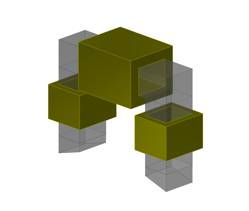
- “Field computation“, that allows predicting:
- Eddy current density and electric field induced by an ET probe in a conductive component
- Magnetic Induction generated by an ET probe in the component, the air, or the sensor itself
- “Probe Response“: to compute Normalized Impedance diagram of the ET probe versus frequency and Lift-off signal of the ET probe
- “Inspection Simulation 3D“: in order to simulate the inspection of work pieces that include various type of flaws
- “Steam Generator Inspection Simulation“, in order to account for many complex parameters inherent to Eddy Current SG tube inspection
Simulation examples
Specimen
Parametric geometries and 2D CAD profile
The graphical interface allows the user to define the following geometries for the specimen:
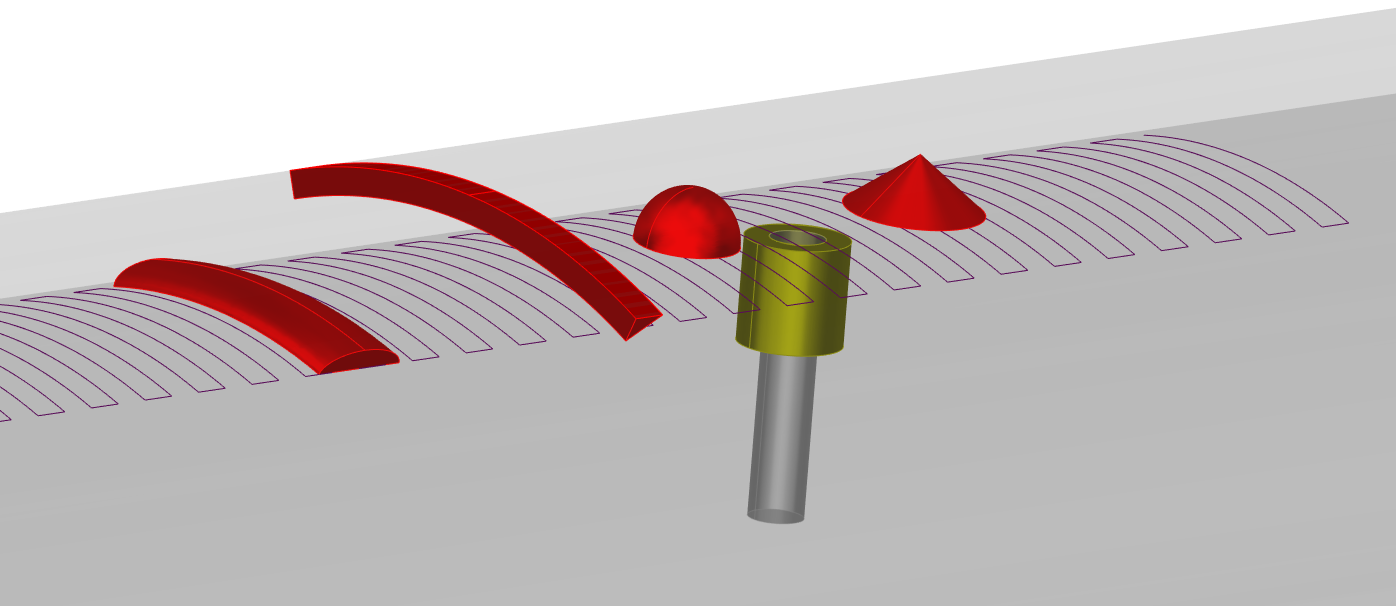
- Field Computation and Inspection Simulation 3D modules: Planar (possibly multilayers) and cylindrical, multilayers fastened plate, parametric weld, turbine groove and root, or 2D CAD
- SG Tube Inspection : Tube straight part, U-Bend, Expansion zone, Section variations, Pilgering distorsion. External elements can be modelled such as support plates (cylindrical, trefoil, quatrefoil), anti-vibration bars, deposit and clogging.
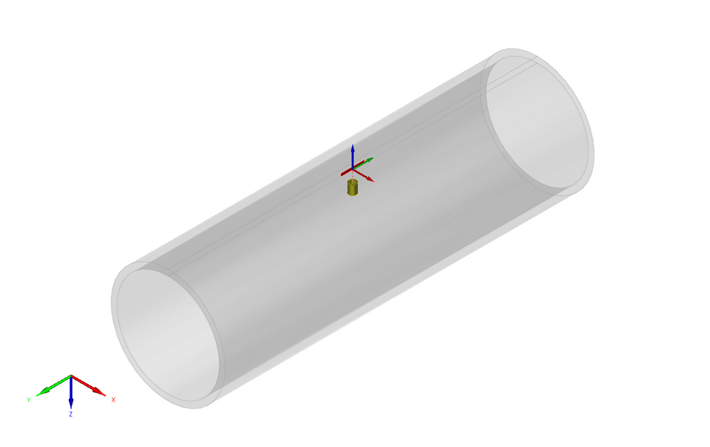
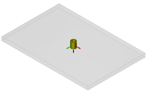
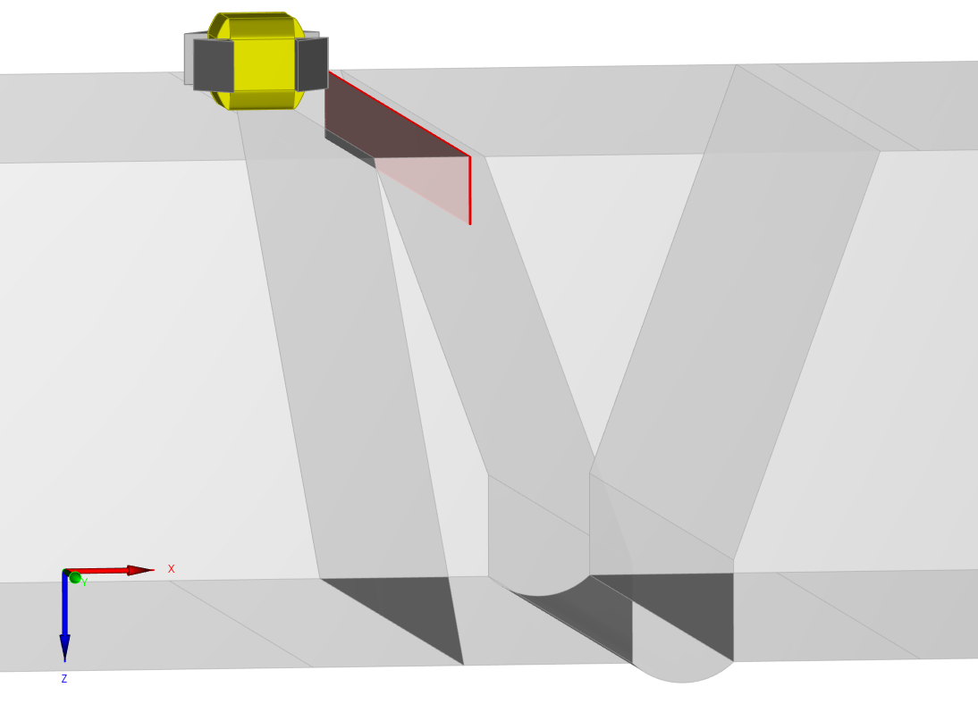
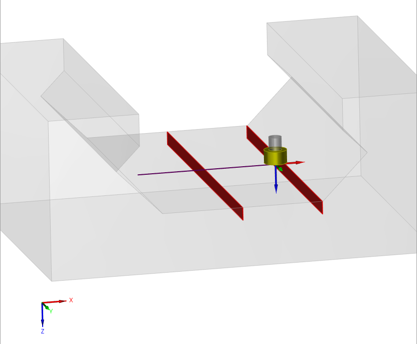
Available component geometries : cylinder, plate, fastened plate, tube expansion, 2D CAD profiles, tube with external elements (deposit, support plate, etc.), weld, blade, root and groove
Materials
User defines the conductivity and the relative permeability of the component (constant values). One can also select directly the material in a predefined database including about twenty classical metals.
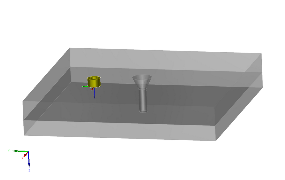
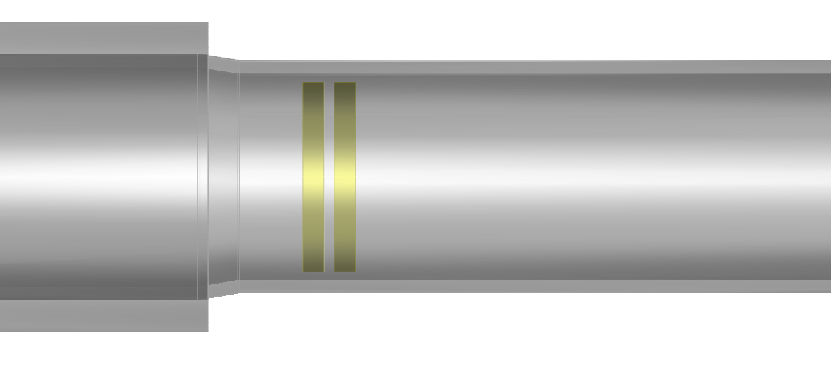
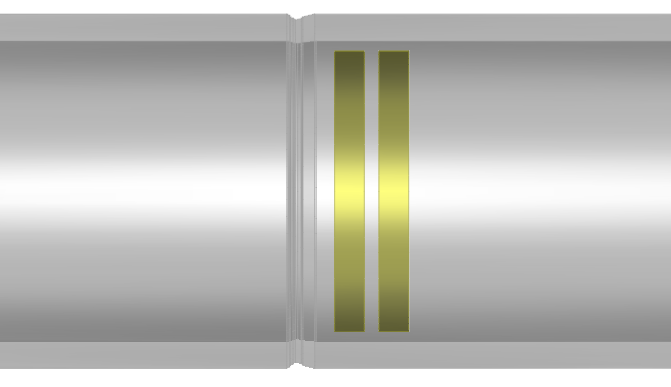
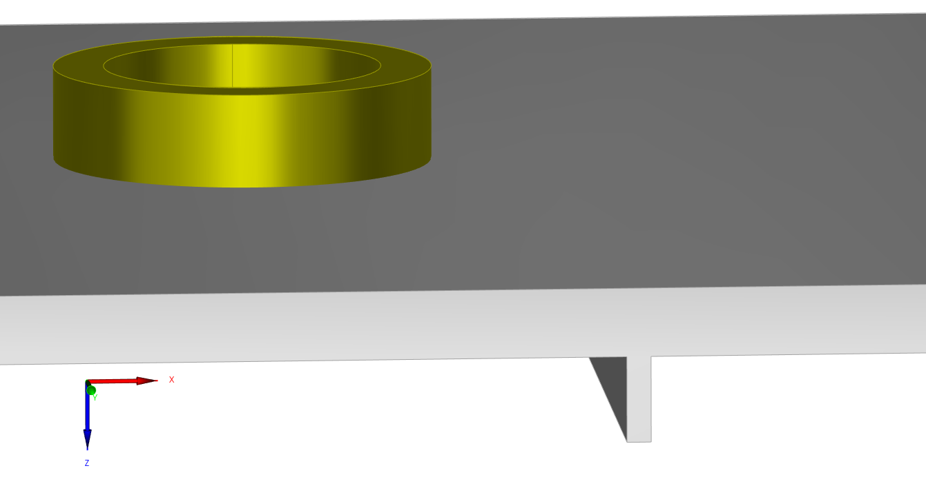
Probes
The ET module proposes a library of numerous types of sensors:
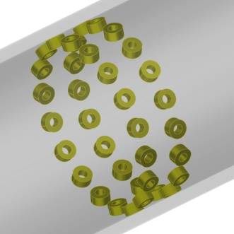
- For planar work pieces inspection: Numerous shapes of coils available such as cylindrical coil, rectangular coil, D-coil, racetrack, meander, spiral circular or rectangular ones (pancake), orthogonal wound sensor so called “+Point Like”, Rototest Like
- For tubular work pieces inspection: Rotating probes with different shapes (as defined above) including +Point Like and Rototest Like and also bobbin coil, encircling coil or sectorial coil (also called “segmental or partial coil”).
- GMR like magnetic sensors,
- ECA sensors (Eddy Current Arrays) that can be configured for surface inspection (on plates) or X-Probe like predefined sensor for tubes
- Emat probe single or multi-elements (Lorentz Forces computation in order to be exported towards the UT or GWT modules)
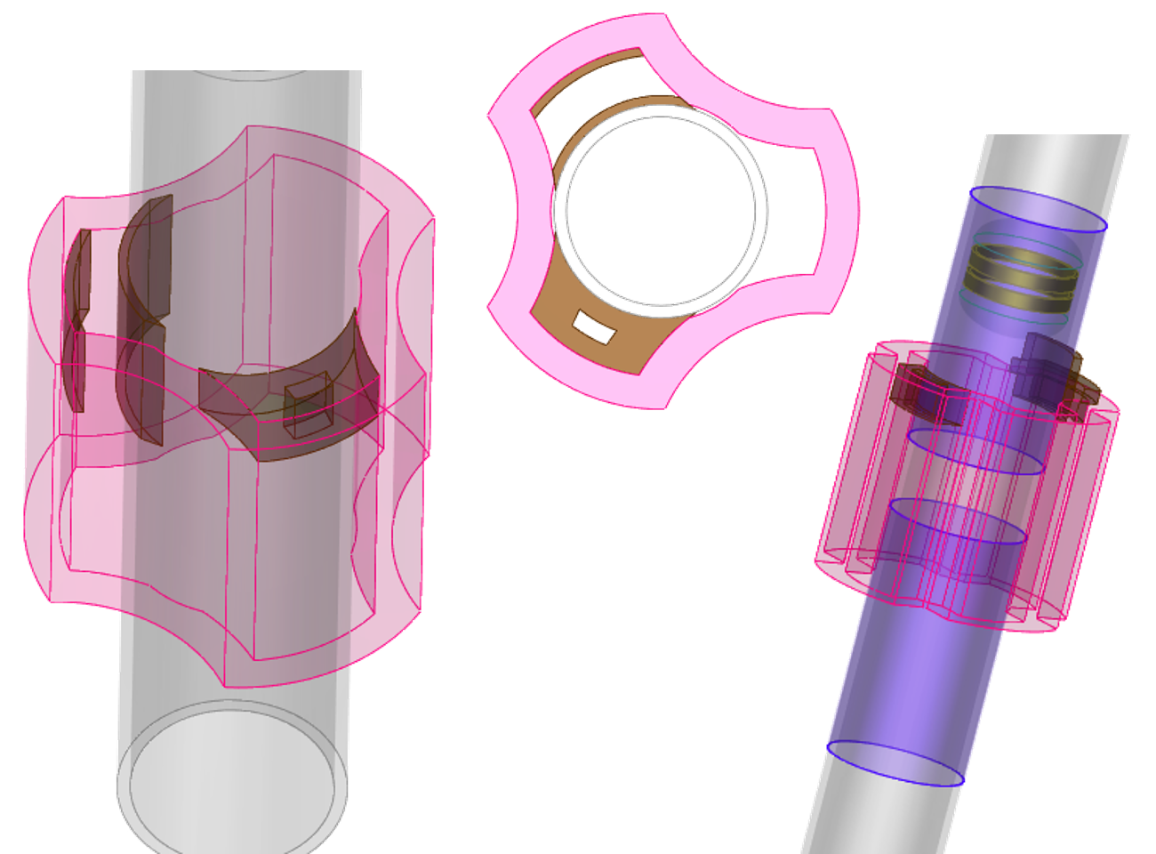
A ferrite core can be added to a coil. The ferrite core can be a cylindrical one, a “C” or E-shaped pot or “U-Yoke“. A shield ring can also be represented. +Point Like and Rototest like come also with their ferrite core (respectively “+” and “D” shape).
CIVA allows the user to simulate multi-sensors and multi-frequencies channels. Several acquisition channels may be defined in a single simulation: Absolute, differential, reflection (separated transmit/receive) at different frequencies.
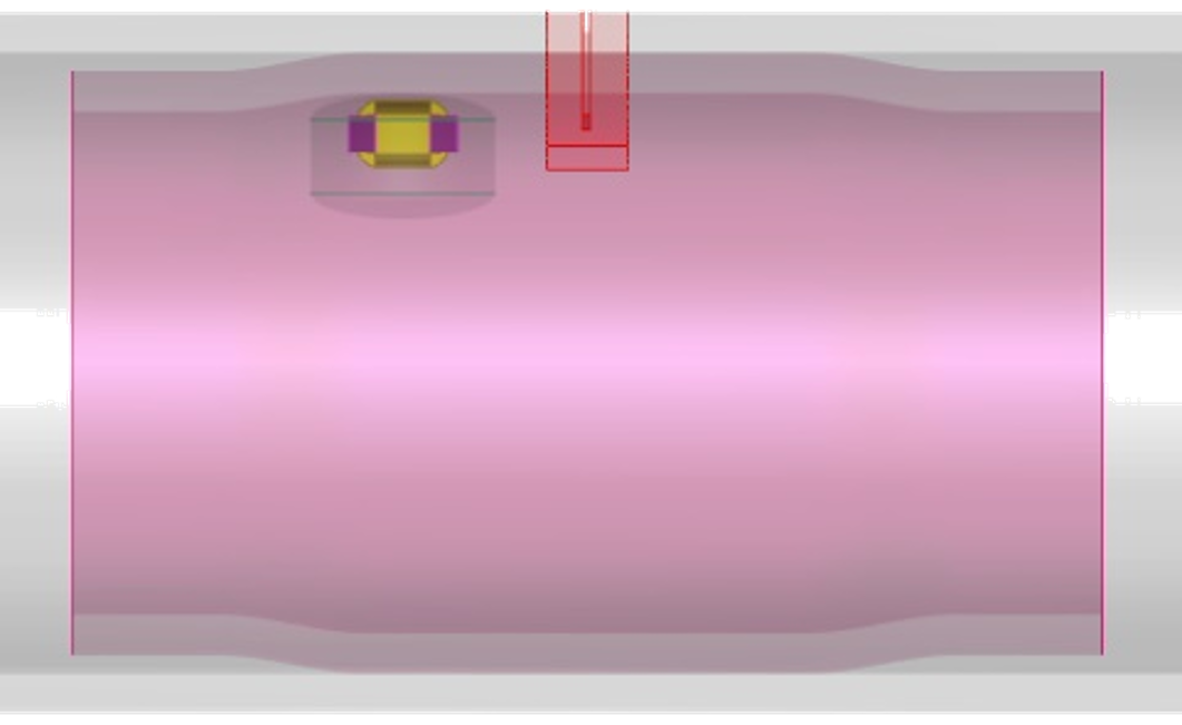
Different phenomena such as variations of lift-off and tilt angles or off-centering in tubes can be accounted for.
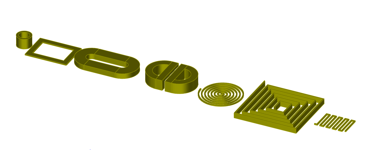
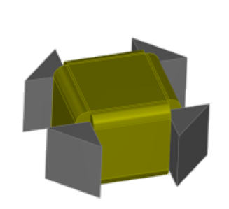
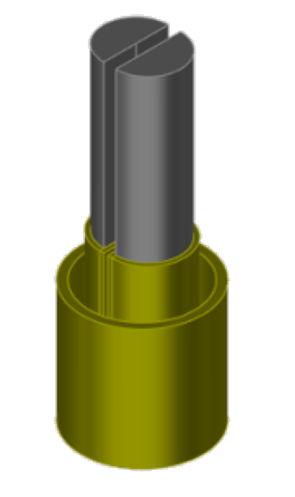
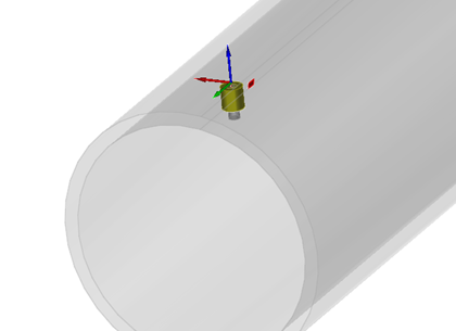
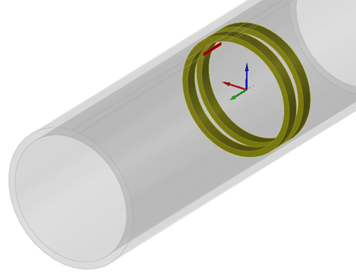
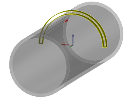
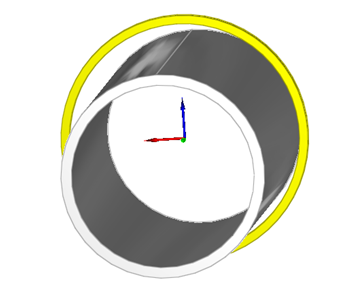
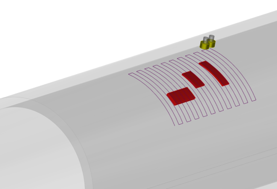
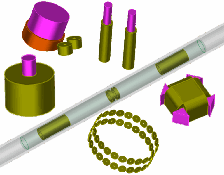
Various ET probe configurations in CIVA: Numerous shapes of coil available, rotating probe or bobbin coil in tubes, bobbin coils, encircling coil, sectorial coil, U-Yoke sensor, Eddy Current Arrays, +Point like, Rototest like
Flaws
Several flaws of different geometries can be defined in the test piece:
- Flat Bottomed Holes in tubes and planar components
- Longitudinal or transverse notches in tubes
- Internal or external grooves in tubes
- Complex notches and drilling profiles in tubes
- Fretting wears in tubes
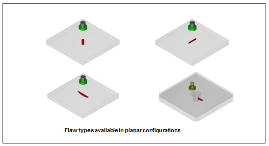
- Parallelepiped flaws in planar or fastened pieces
- Semi-elliptical or quarter-elliptical notches in plates or fastened pieces
- Infinite notch in 2D CAD or complex component profiles
- Bumps in SG Tube module
- Complex wear profiles dues to external elements vibrations in SG Tube module
Flaws can be voids, metallic inclusions (with a lower conductivity than the surrounding material) partially filled with materials (“bridge contacts” defect type).
Notches in plates can have a skew angle. Infinite notches in CAD profiles can be tilted. Several flaws can be combined (i.e. crossed), which can allow representing a complex profile.
Defects can be surface breaking (i.e. positioned on the inner side or on the opposite side), or sub-surface (embedded inside the work piece with a defined ligament).
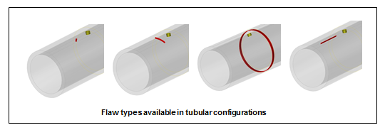
Complex defect profiles available in tubular configurations
Results
Field and impedance computations in flaw-free components
The field computation and probe response modules propose fast analytical calculation tools for flaw-free work pieces. Several quantities can be displayed: Eddy-current density, electric field or magnetic induction. The normalized impedance diagram of a probe can be plotted for various working frequencies facilitating finding the best operating frequency.
The lift-off signal (i.e. impedance change due to lift-off variation) in the impedance plane can be also calculated and displayed.
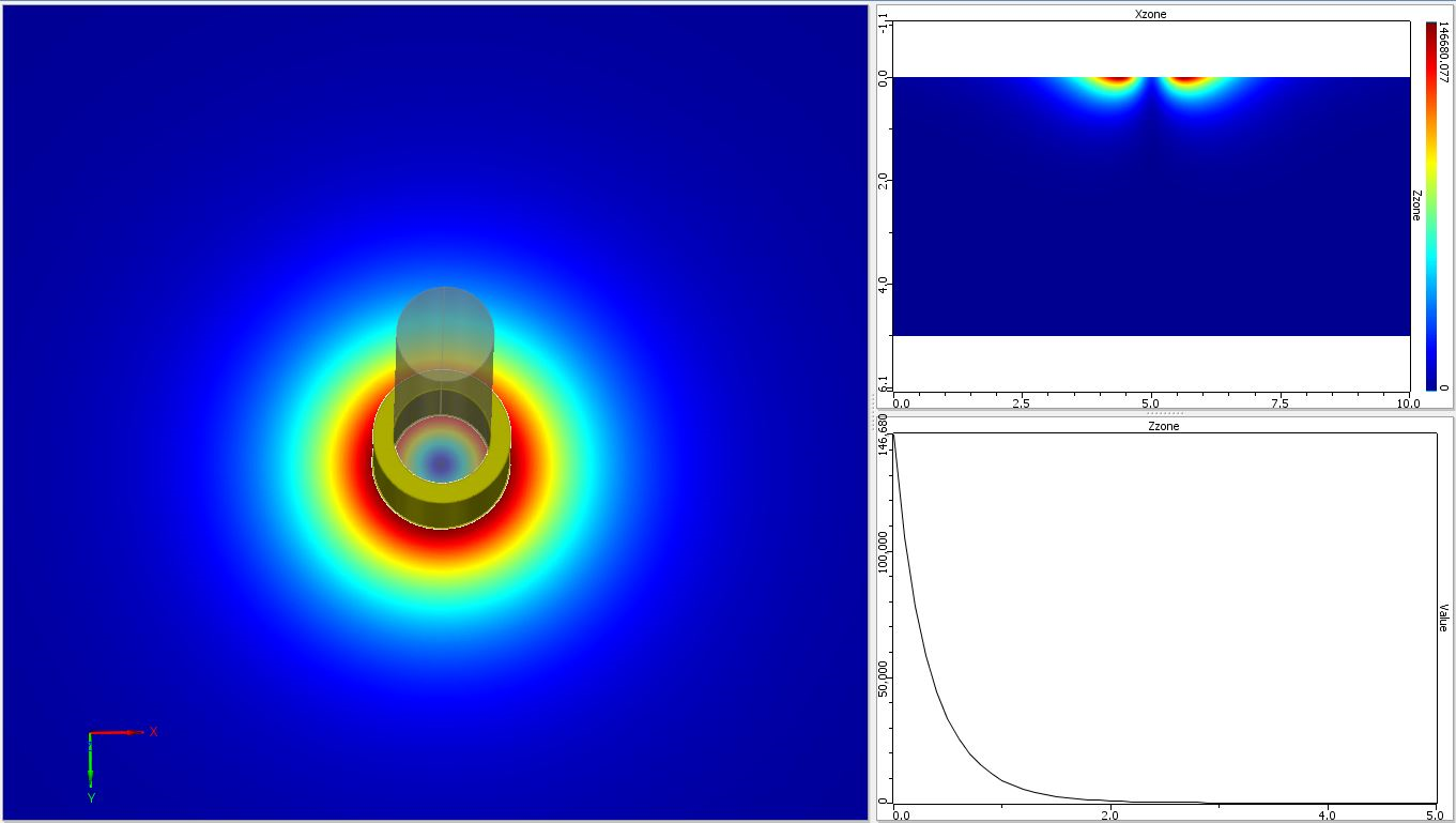
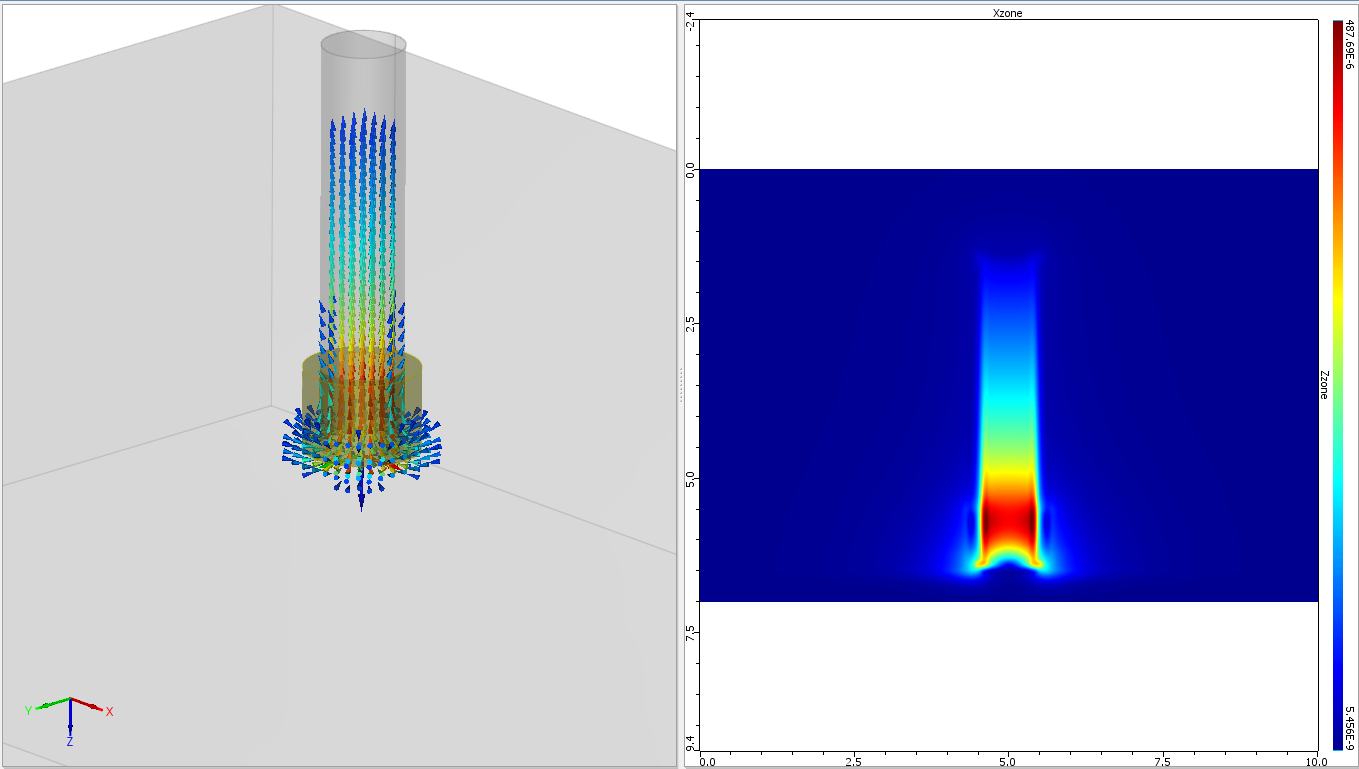
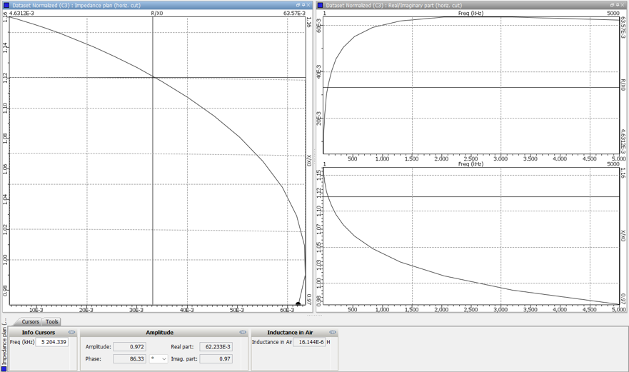
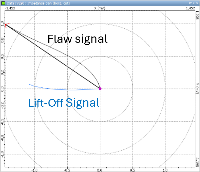
Some results available in the Field Computation and Probe Response modules: Eddy Current induced in the specimen, Frequency response of the sensor (normalized impedance diagram)
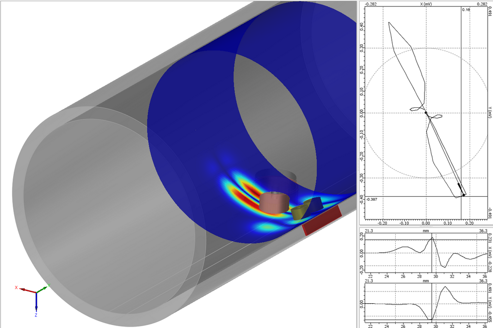
Inspection Simulation 3D
In Inspection Simulation 3D, the user can simulate the inspection of components having one or several defects (possibly combined), selected among the available list of defects presented above. The sensors scanning can follow linear trajectories, transverse or helical ones.
In planar or fastened specimens, several materials at several conductivities (but non-ferromagnetic) can be defined in different layers. Users can defined several defects, potentially crossed and skewed.
In this module, in tubular work piece, only a single material will be assigned. This one can be ferromagnetic. In particular, CIVA can model the Remote Field Technique for ferromagnetic tubes inspections (so-called RFT).
A multi-channel mode gives the possibility to compute in one shot of simulations, several acquisition channels (absolute, differential…) at one or different frequencies.
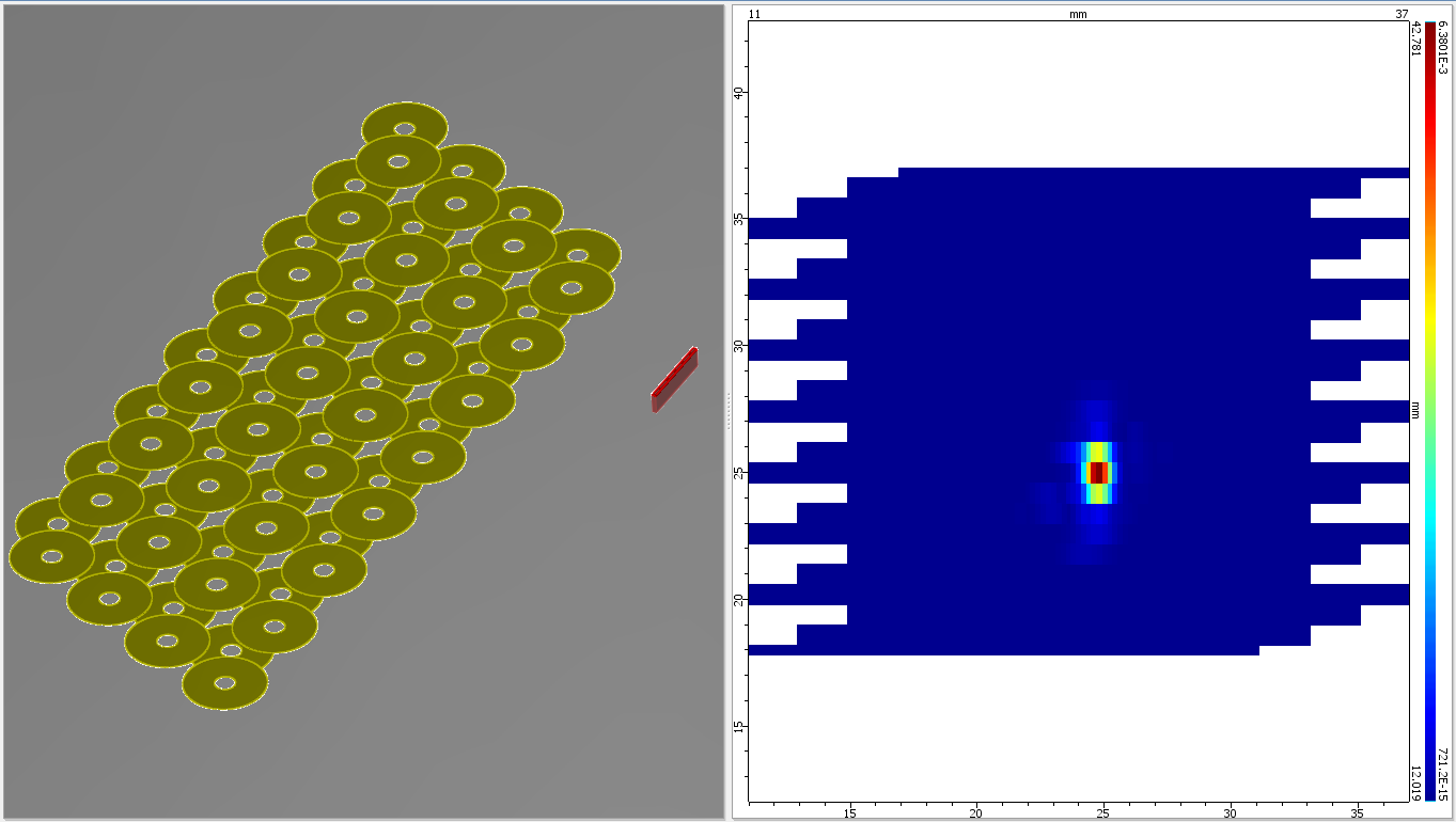
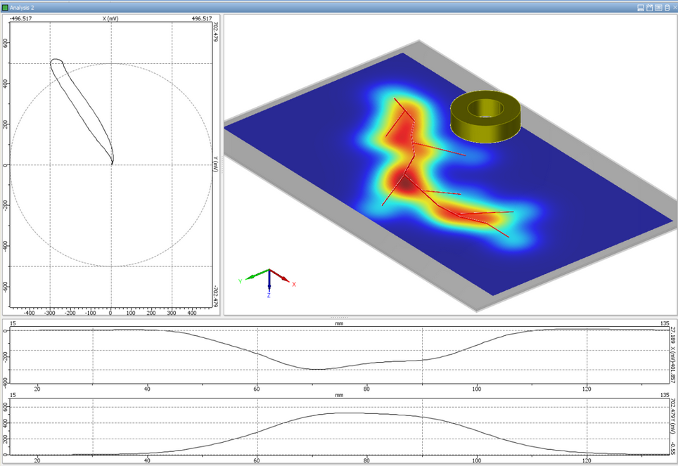
Cscan of a simulation of a planar component inspection with crossed flaws
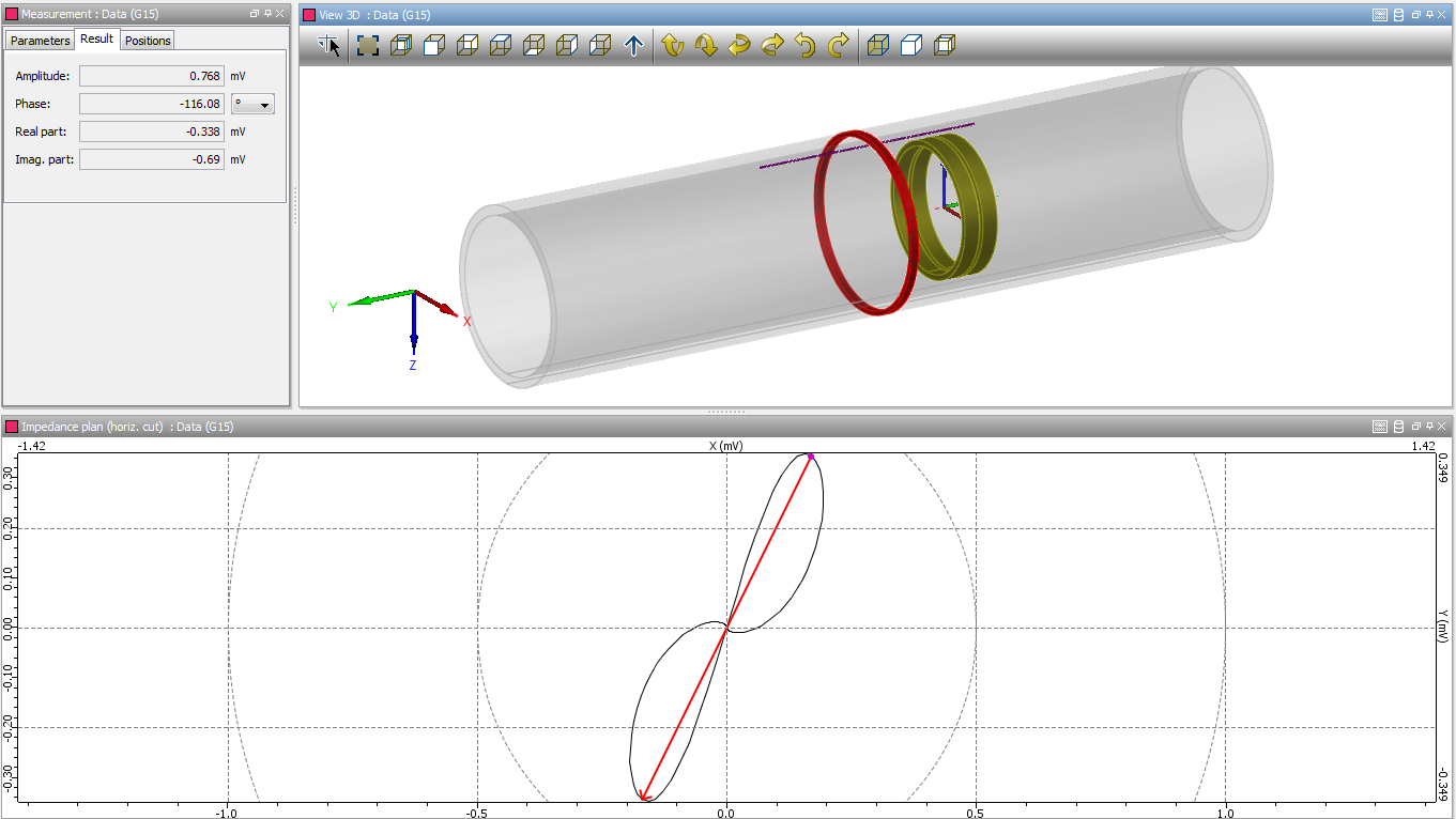
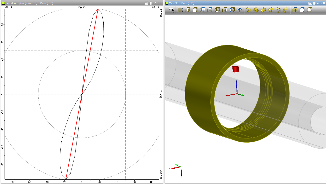
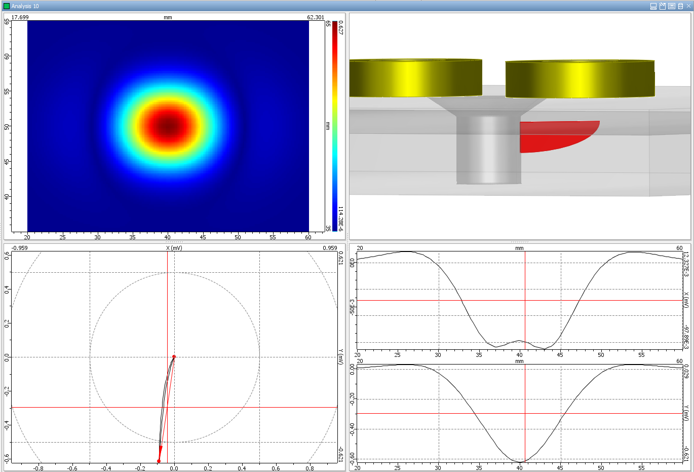
A dedicated post-processing tool displays the impedance variation signal due to the flaw(s). Results are displayed with a Cscan colored chart or conventional curves in the impedance plane. The environment provides access to classical results for an ET analysis (Amplitude, Phase, X and Y channel, Impedance plane) as well as other tools to process data: Calibration, Frequency mixing, Interpolation, Balancing, and Filtering.
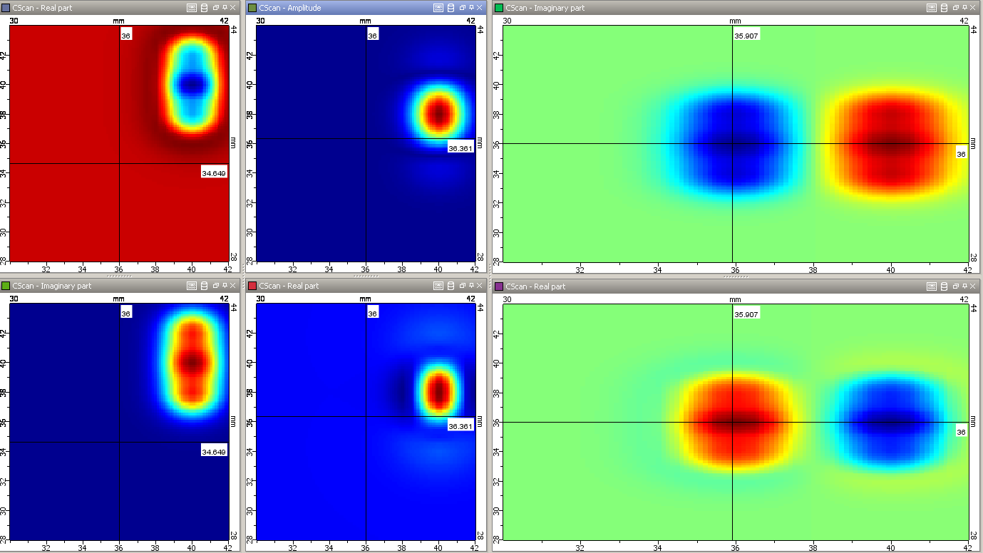
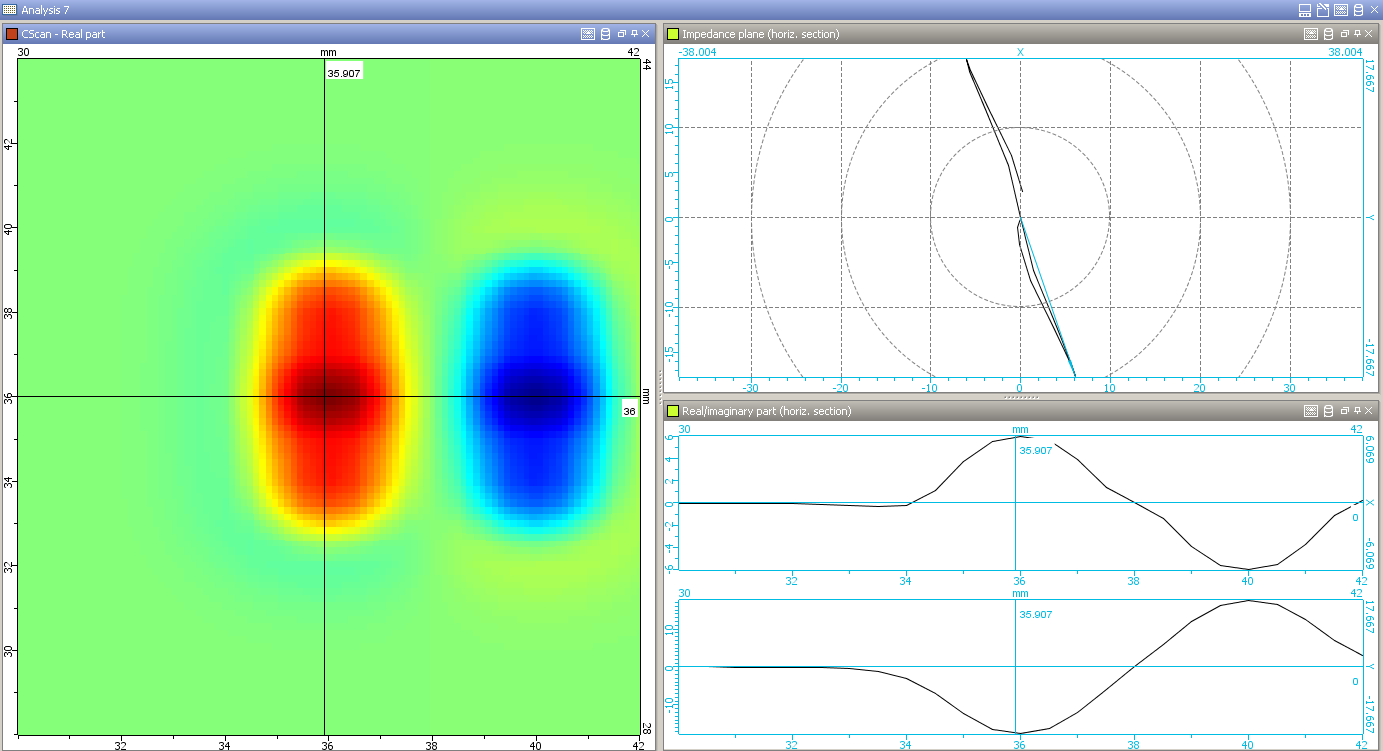
Analysis environment: Cscan, Impedance plane, display of different channels
CIVA can also simulate Pulsed Eddy Current Testing (PEC), a technique mainly used for corrosion or other applications involving large lift-off or depth inspection. CIVA can simulate various pulse profiles and will compute the received signal for different probe configurations. Analysis is then made through various quantities (C-Scan, A-Scan, FFT, etc.).
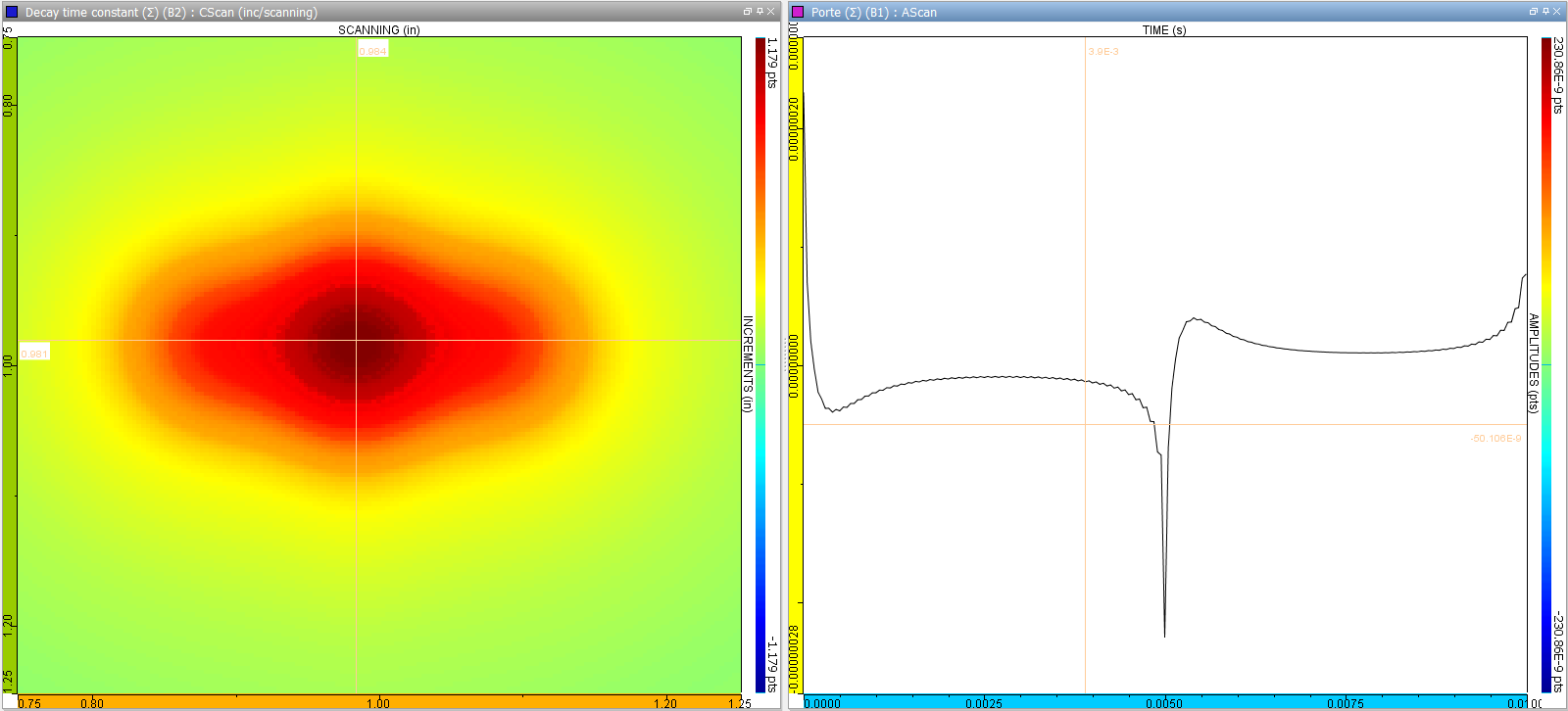
Pulsed Eddy Current Cases
To understand and quantify the impact of influential parameters on a NDT inspection, parametric studies in CIVA are particularly adapted since it is easy and fast to precisely change and monitor parameters. Based on a first set of computations, metamodels can also be calculated in CIVA, which provides extensive new results to the user in real time, as well as powerful analysis tools such as multi parametric analysis and sensitivity analysis to evaluate the relative impact of influential parameters.
POD calculations (Probability Of Detection) are available, based on the accounting of uncertain input parameters. Single or Array of POD curves can be plotted inside CIVA.
Inspection Simulation SG Tube
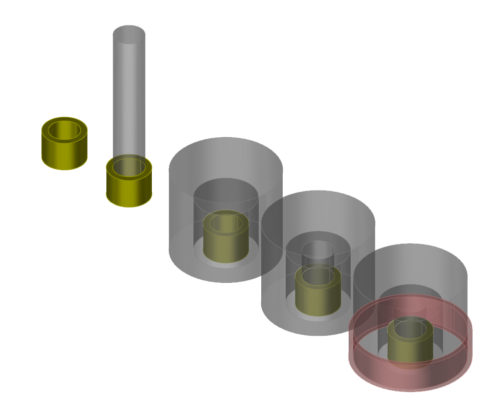
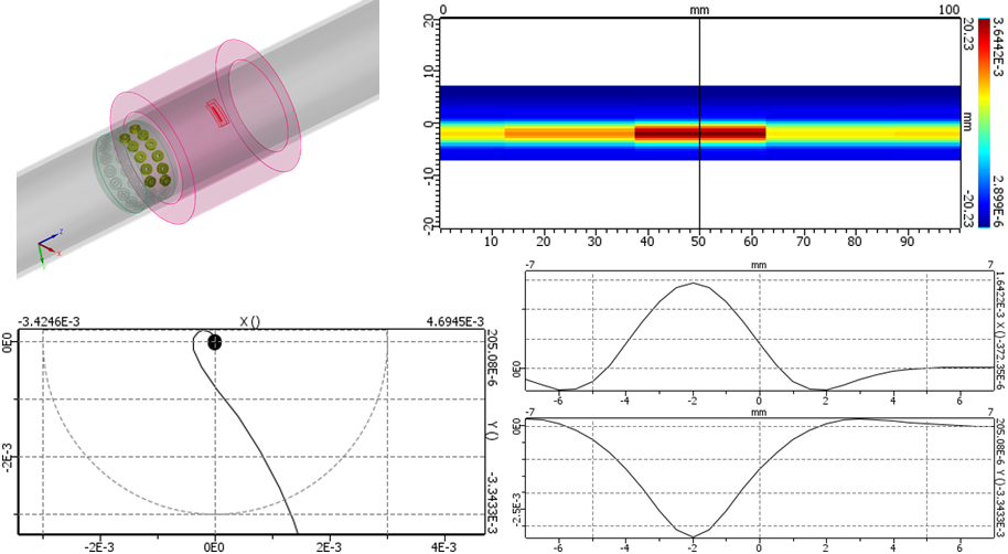
In the SG Tube Inspection Simulation module, many complex parameters inherent to Eddy Current SG tube inspection can be accounted for : U-Bends, expansions, support plates, clogging, deposit, wears, sleeved tubes, etc. Many probes are available in this module: Bobbin coils, Rotating probes such as transverse, longitudinal or +Point probes, Eddy Current Arrays, RFT probe. Results are given in the impedance plane or for X and Y channels versus the probe position.
Various probes available in the SG Tube module
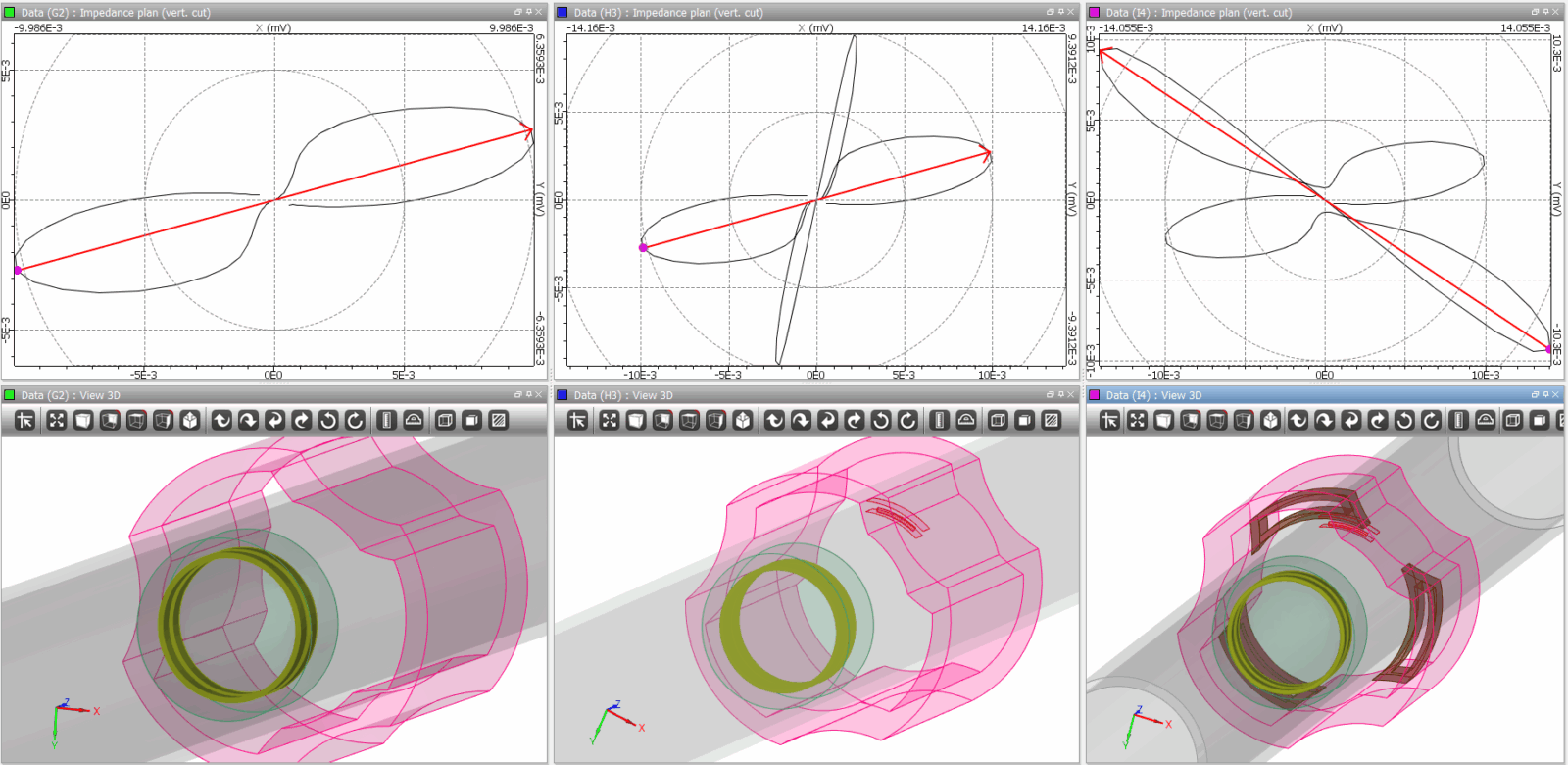
SG Tube inspection configuration with trefoil support plate, without defect, with defect, then with defect and clogging
SG Tube inspection configuration in U-Bend zone with anti vibration bar

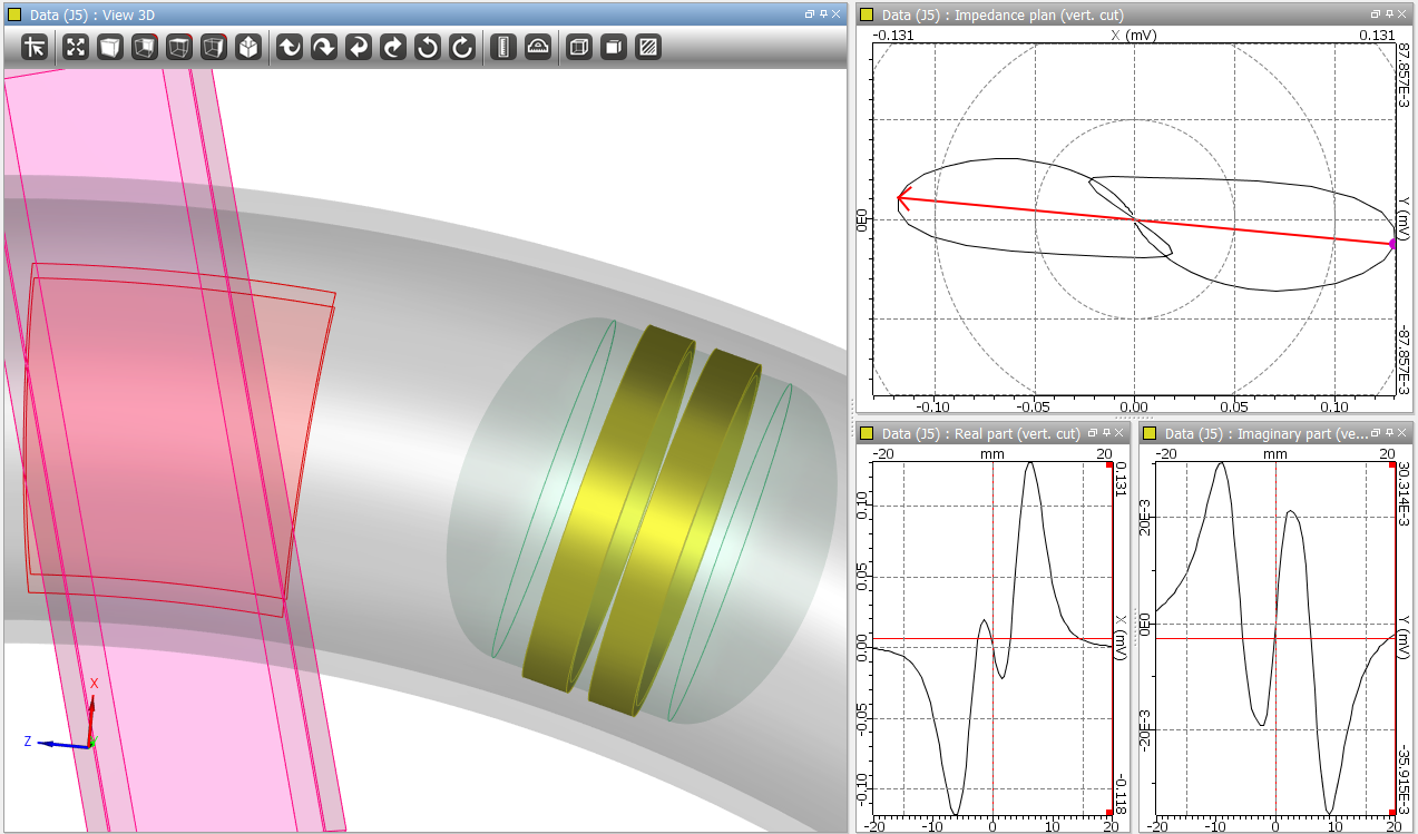
SG Tube inspection configuration with a sleeved tube, a tilted probe riding the expansion zone, and with an ECA