UT simulation tools include:
- "Beam computation": Beam propagation simulation
- "Sensitivity coverage": To compute sensitivity maps for a given scan plan
- "Inspection Simulation": Beam interaction with flaws or specimens
User can simulate a whole inspection process (pulse echo, tandem or TOFD) with a wide range of probes (conventional, Phased-Arrays or EMAT), components, and flaws.
Simulations examples
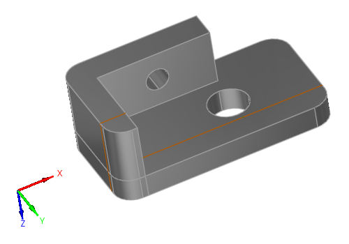
specimen
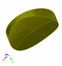
Parametric geometries and CAD files:
The graphical interface allows the user to define the following geometries for the specimen:
- Canonical ones: Planar, cylindrical, conical, spherical
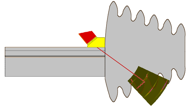
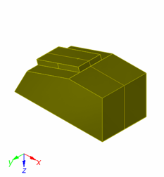
- Predefined component: Nozzle, Butt, bimetallic and Tee Weld templates (13 different bevel profiles available), Turbine blade root and groove, Through Wall Penetration, Elbow, Plates with fasteners
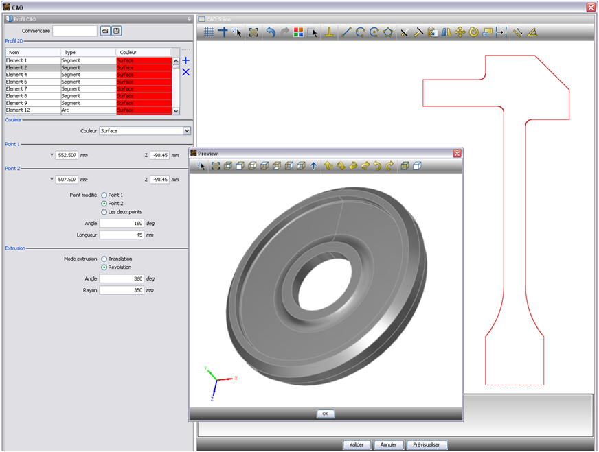
- 2D CAD files containing a profile and generation of the 3D geometry either by translation or rotation of the profile: The profile can be homogeneous or heterogeneous. It can be defined either by CAD import (DXF or IGES format) or directly drawn by the user inside the 2D sketcher of CIVA
- 3D CAD files (IGES or STEP format): Homogeneous or heterogeneous solids, assembled structures with different solids
- Images (such as macrographs) can be imported in CIVA interface to help specimen definition and positioning
- “Depressions” profiles can be described in planar and cylindrical components in order to describe easily local warps
CIVA can also export specimen geometries in IGES format.
Materials:
The component can be solid or fluid, homogeneous or made of several layers (e.g. cladding). Each layer may be isotropic or anisotropic, of arbitrary symmetry and orientation. Materials available are not only metallic ones but can also be fiber composites or granular composites (e.g. concrete). A model called “polycrystalline” allows defining monophasic or biphasic grain structure based on the knowledge of the grain size. This model includes the calculation of attenuation laws and structural noise parameters. Finally, simulations on “coarse grains" structures can be done by creation of volumes with the help of Voronoï diagrams. This model allows reproducing beam deviation phenomena, typical of coarse grain structures (e.g. cast stainless steel).
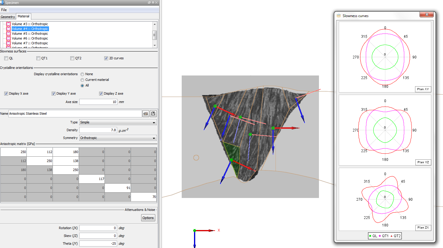
A model of continuously variable anisotropic properties of a volume has been implemented. This has been introduced in order to better account for ultrasound propagation in complex welds. This model is based on the “Ogilvy” theory relative to the grain orientations distribution in austenitic V welds.
Regarding fluids, it is possible for 2D CAD components to account for temperatures gradients in such inhomogeneous fluid media and to account for a flow with speed gradient.
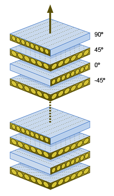
A composite « perspective » (i.e. dedicated environment within CIVA) gathers all features specific for composite materials. It helps to define easily flat or curved composites, stiffeners, stacks of composite plies, ply waviness or delamination. It is also possible to define a pure epoxy layer in between CFRP plies and to account for ultrasound interferences between plies, source of structural noise. Following the options selected, the computation will be then described by semi analytical methods in CIVA UT or in an optional module CIVA FIDEL2D that relies on a coupling between CIVA and a 2D Finite Difference Code called FIDEL 2D and developed by AIRBUS Group Innovations.
Probes
A wide range of UT probes (standard and advanced designs) can be handled:
- Single element, dual element, Phased-arrays (see Phased Arrays section), TOFD, Tandem probes or EMAT single elements and Phased-Arrays (EMAT modeling involves a coupling with CIVA ET)
- Contact or Immersion testing
- Rectangular, circular or elliptical radiating surfaces
- Focused probes via either shaped surfaces or probes with added acoustic lens
- Planar or spherical / bifocal / Fermat focusing surfaces
- The pulse emitted by the crystal surface can be considered as uniform or variable through an apodisation function
- For contact transducers without wedge, the pulse can be in piston mode or with shear polarization ("S0°")
- A library of industrial probes (single element or phased-array) can be directly loaded from a database
Phased array Settings
A variety of phased-array transducers are available:
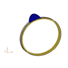
- Annular, "Daisy" probe type with mirror, 1D Linear, 2D matrix, 2D sectorial or elliptical patterns, EMAT Phased-Array
- Encircled or Encircling curved arrays for tube inspection
- Flexible phased-array probe (in contact with parametric or CAD specimen, linear or matrix pattern)
- Custom phased-array (manual or random arrangement of elements)
CIVA allows the user to compute delay laws and sequences of delay laws for standard and advanced phased-array techniques:
- Common or independent definition for transmitting and receiving elements
- Electronic scanning, simple (such as Linear Scan) or advanced (e.g. variable aperture at transmission or reception)
- SAUL algorithm
Delay laws can be computed for specimens of arbitrary geometry (canonical or complex) and materials (homogeneous or heterogeneous materials, isotropic and anisotropic) from the simplest to the most advanced configuration:
- Sectorial scanning
- Focusing on one or several arbitrary points
- Electronic scanning
- Application of non-uniform amplitude laws (influence of non-homogeneous element responses, beam apodization)
- Application of dynamic delay laws (in case of complex geometries, delay laws can be computed independently for each probe position along the scanning axis)
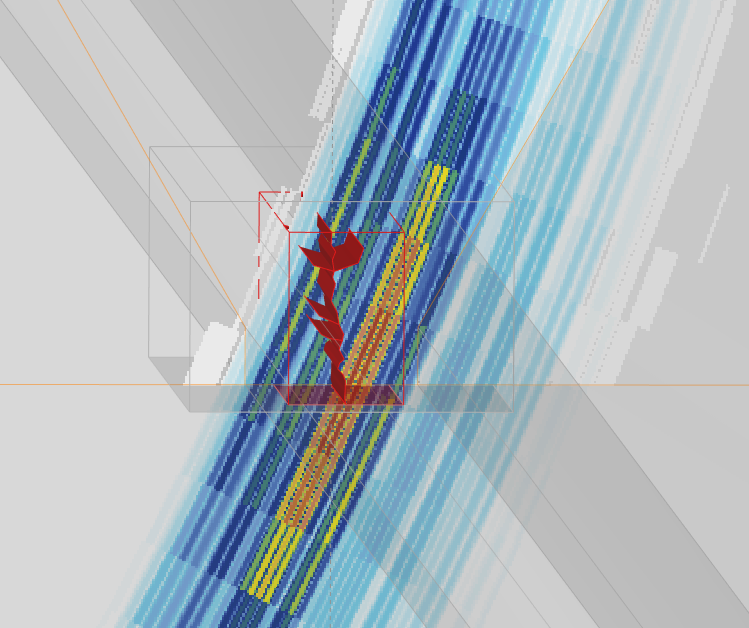
CIVA also proposes Synthetic Focusing with the Total Focusing Method algorithm that can be applied to allow optimal reconstructions of flaw echoes and specimen boundaries. This processing allows, from an acquisition file or a phased-array simulation, the reconstruction of an image by combining signals in order to have the best focusing on a given zone. The classic TFM algorithm based on amplitude summations is available, as well as other ones based on phase and coherence factors such as PCI, Sign Coherence Factor, or Phase Coherence Factor. Main associated acquisition types are Full Matrix Capture or PWI acquisitions. TFM can be done for a single position of the transducer or associated with a mechanical scanning. In this case, Cumulated or Sliding TFM reconstruction modes are available. Adaptative TFM (ATFM) can also be tested in CIVA. Sensitivity maps for the different TFM reconstruction modes can be displayed to help select the most relevant modes.
Flaws
An arbitrary number of flaws may be inserted into the component; these defects can be:
- Calibration defects: side-drilled holes, flat-bottom and hemispherical holes
- Planar defects, of arbitrary size and orientation, rectangular, elliptical, semi or quarter elliptical
- Orthoradial defect in the connection zone of a nozzle
- Multifaceted defects, 2D CAD contour defects, Branched defects
- Volume flaws such as spherical pores or solid inclusions (cylindrical, spherical or elliptical shapes)
Results
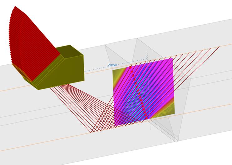
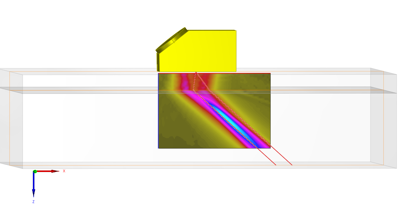
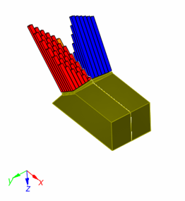
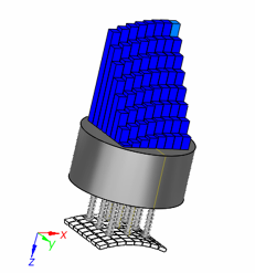
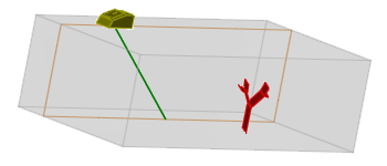
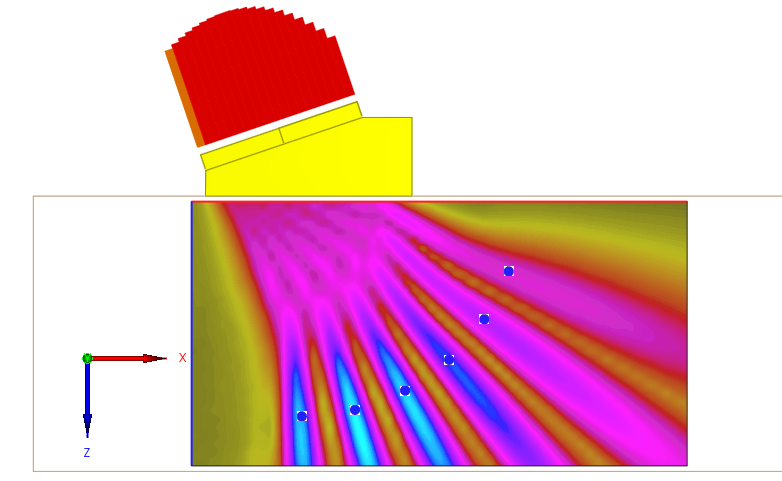
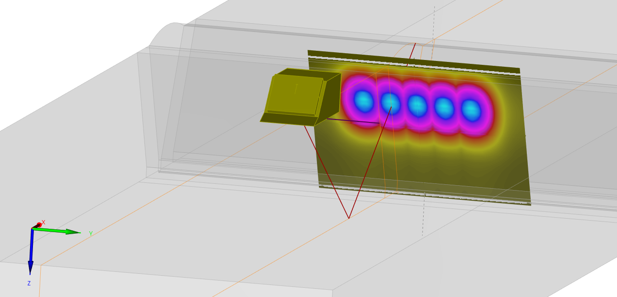
Beam calculation
A first module simulates the ultrasonic beam in the specimen and if asked in the coupling material.
The calculation can account for multiple skips in the component. It is also possible to define manually the list of modes to account for in the computations (number of skips, internal reflections, mode conversions between layers, etc.).
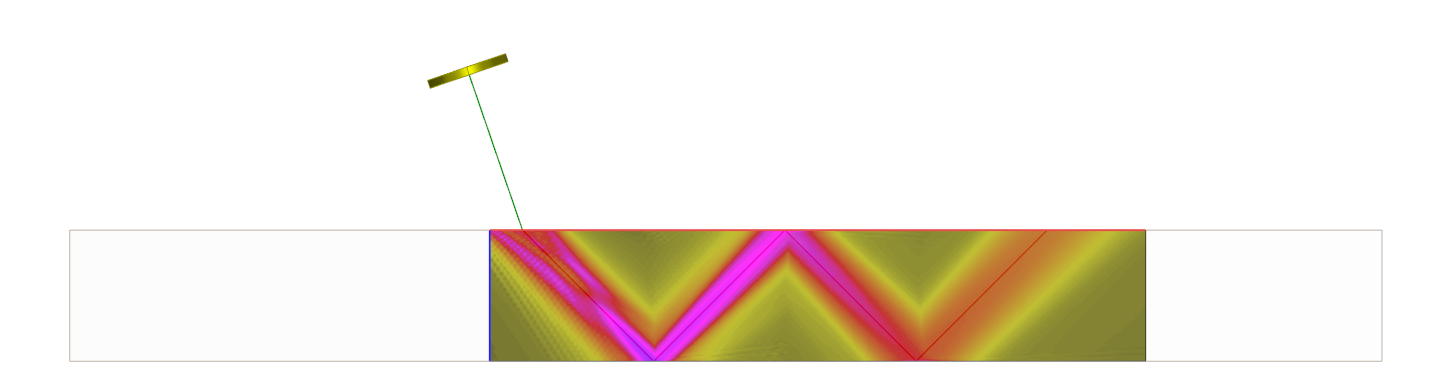
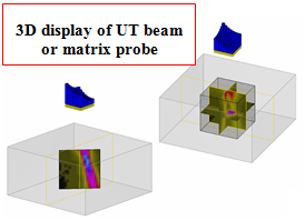
The beam can be displayed in the specimen as an amplitude color coded image or as an iso-amplitude surface. Local orientation of the beam and wave fronts can be displayed (and saved as animated files, AVI format). For phased-array probes operating in multiple shots mode (e.g. sectorial scan), both single beam and cumulated beam can be displayed.

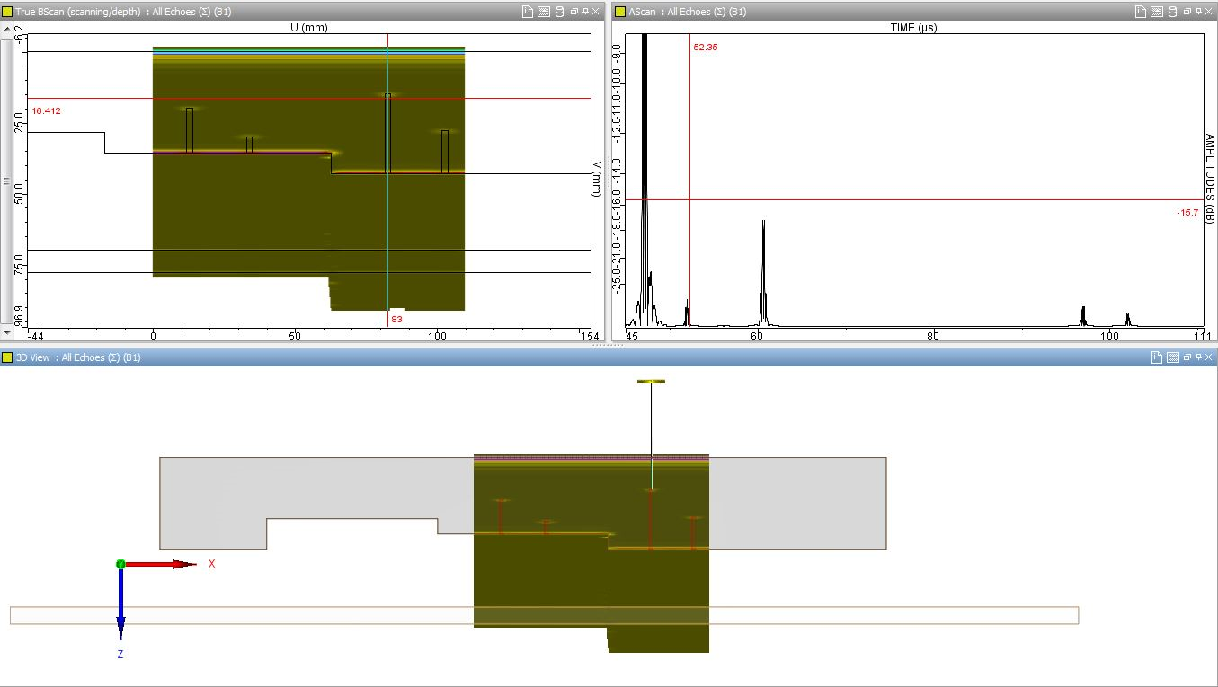
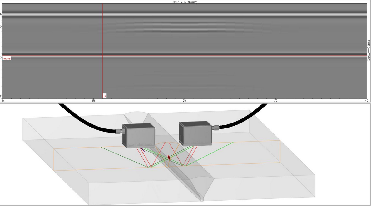
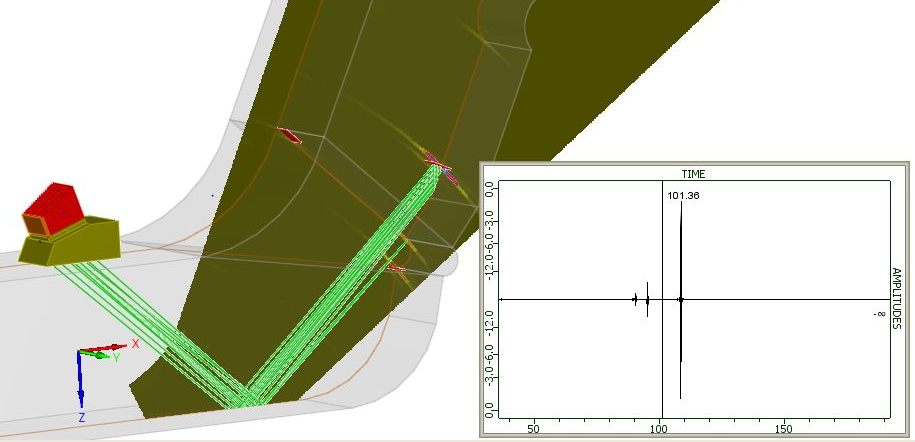
Inspection Simulation
This module simulates the beam-defect interaction and predicts the amplitude and the time of flight of various echoes: direct echo, corner effect, tip diffraction echo, etc. The number of skips has no limit. It can also calculate echoes scattered back by the geometry (backwall, entry surface and interior specular interfaces echoes), takes into account mode conversions and in some cases creeping waves.
For TOFD configuration, direct tip echoes generated by the edge of the defects are simulated as well as lateral waves. The list of modes allows the user to choose which modes to calculate.
To understand and quantify the impact of influential parameters on a NDT inspection, parametric studies in CIVA are particularly adapted since it is easy and fast to precisely change and monitor parameters. Based on a first set of computations, metamodels can also be calculated in CIVA, which provides extensive new results to the user in real time, as well as powerful analysis tools such as multi parametric analysis and sensitivity analysis to evaluate the relative impact of influential parameters.
POD calculations (Probability Of Detection) are available, based on the accounting of uncertain input parameters. Single or Array of POD curves can be plotted inside CIVA.
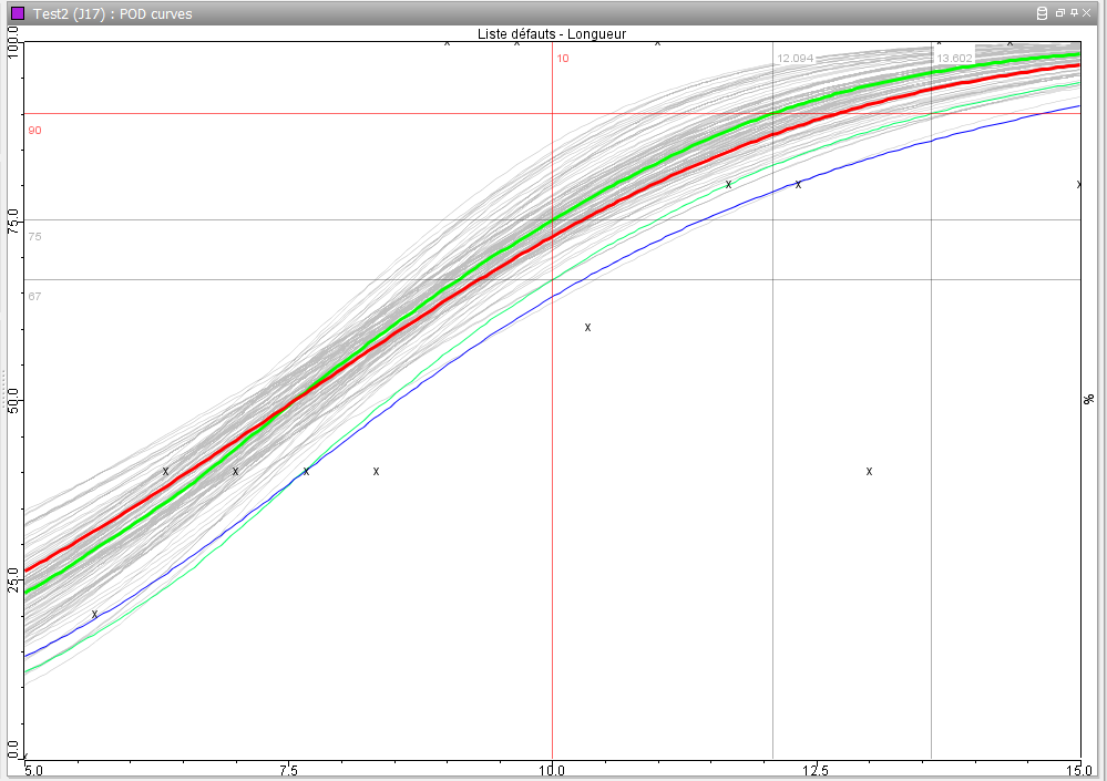
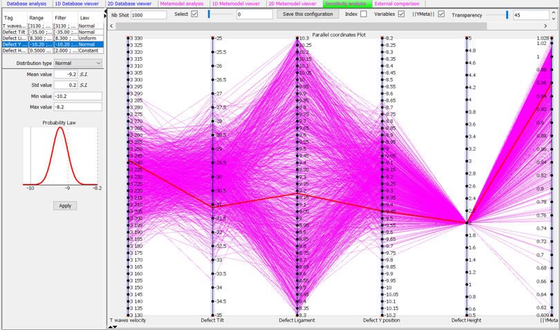
Inspection simulation results: S-scan, A-Scan, POD curve, Parametric and sensitivity analysis with metamodels, etc.
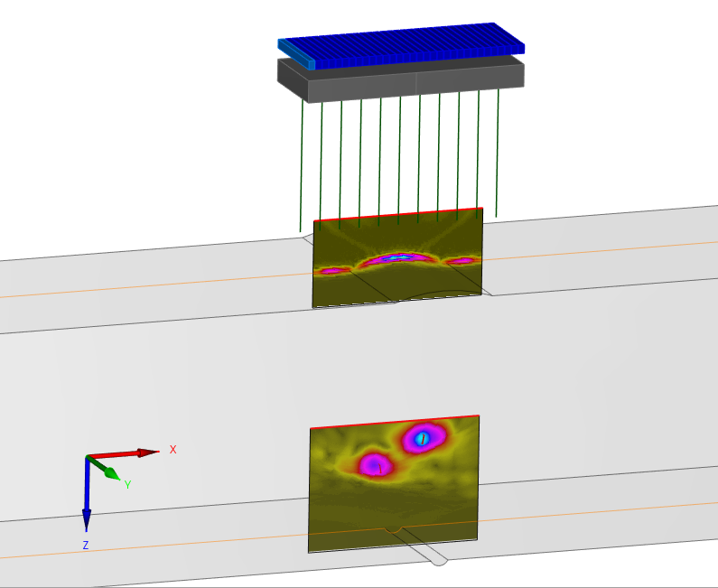
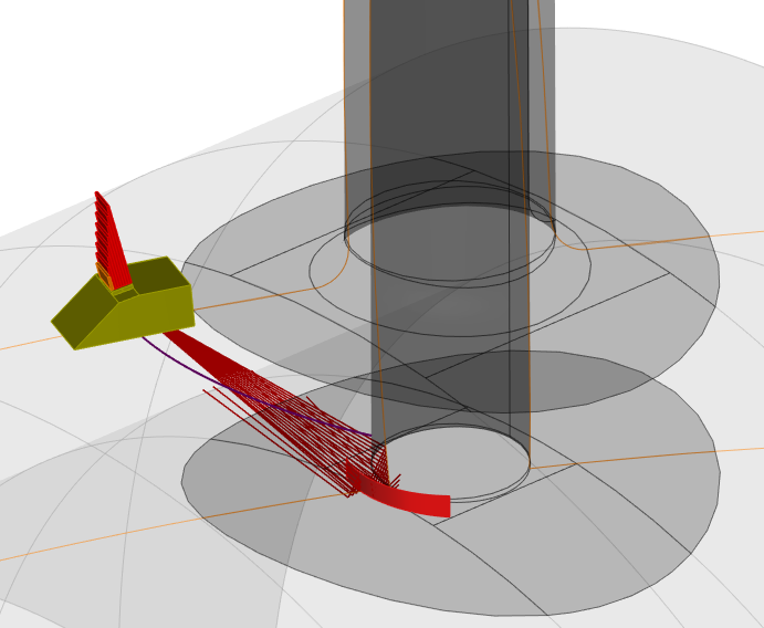
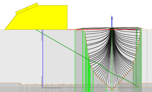
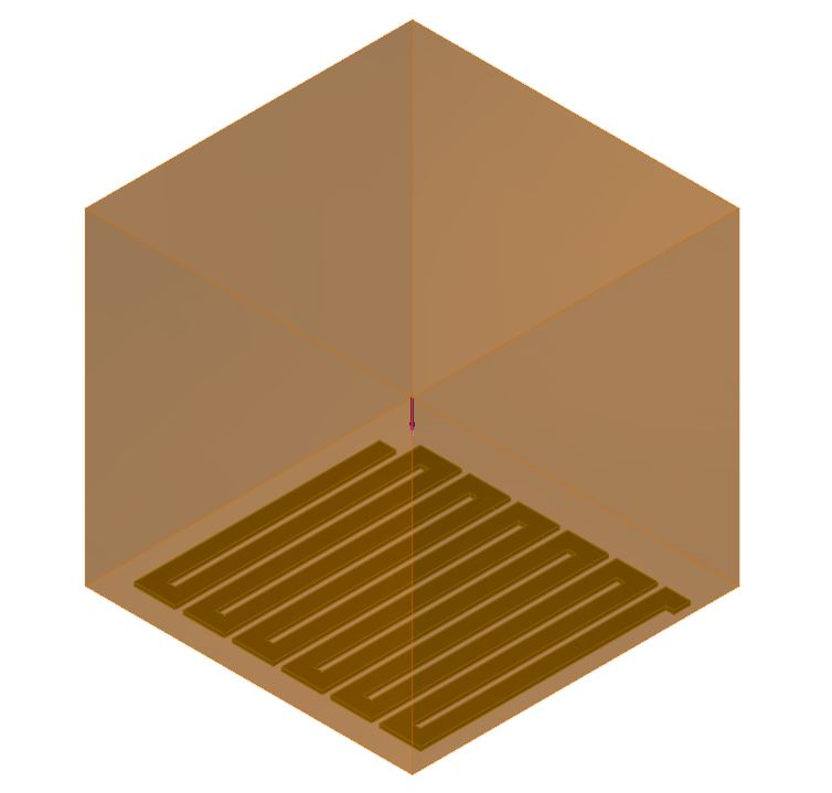
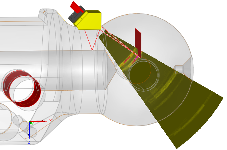
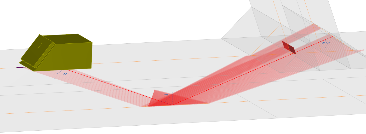
Zone Sensitivity Coverage & Ray tracing
A sensitivity coverage tool is available. It can cumulate field computations in Transmission and Reception on one image defined in a region of interest for a given scan path. It can account for the evaluation of the sensitivity to a certain defect orientation.
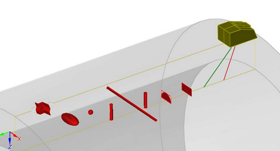
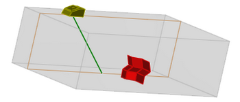
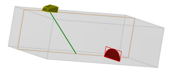
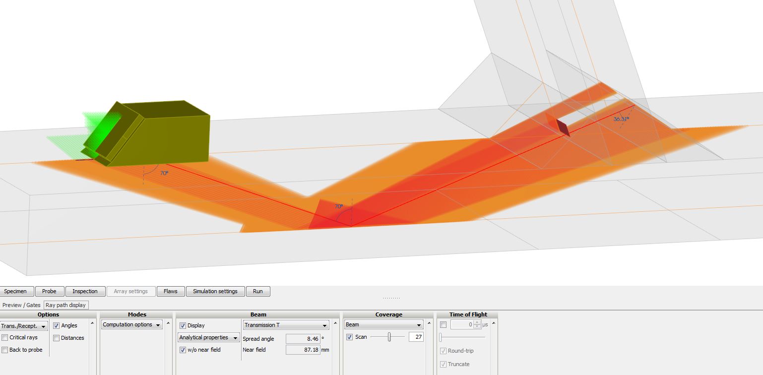
An advanced ray tracer is connected to CIVA simulation modules. It displays the different wave modes propagated and reflected (L waves, T waves and mode conversions), it can display time of flights on the UT path which can help the understanding and analysis of some signals, reflections, displays time of flight, etc.). Moreover, this tool can display in real time a simple but realistic representation of the ultrasound beam for a given sensor position (with divergence angle and near field distance) but also to estimate the zone coverage for the whole set of scanning positions (and for the different shots if a PA probe is used) which makes possible to evaluate at a glance the covered area with the defined settings. The incidence angles of the beam on the specimen boundaries and the defects are also represented.
Analysis tools
Results are provided as classical UT data (A-Scan, echodynamic curves) or more advanced images (B-Scan, C-Scan, S-Scan, E-Scan, etc.) that can be reconstructed and surimposed on the work piece, allowing an optimal understanding of physical phenomena. Results can be calibrated versus a reference flaw in a block. DAC curves can be easily calculated thanks to an integrated tool, both for single element and Phased-Array probes in sector scan or linear scan mode. CIVA will then compute and apply the Time Corrected Gain correction to process and calibrate the simulation data.
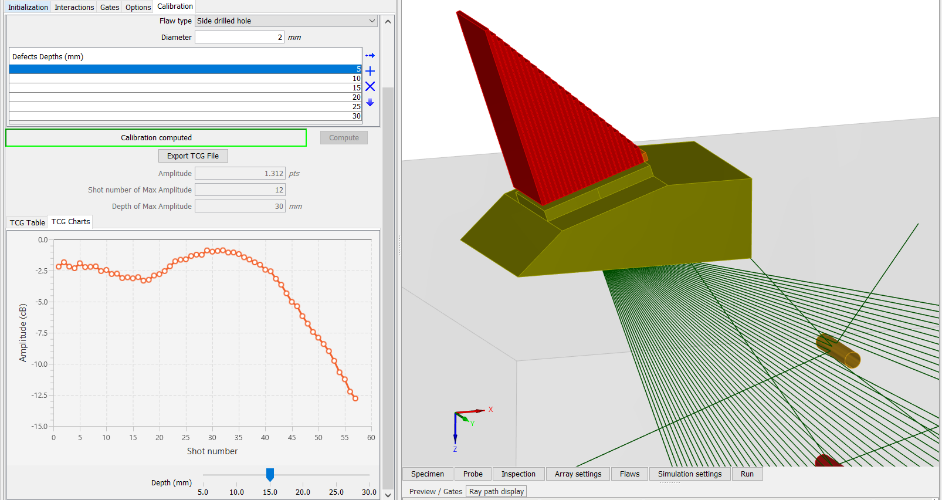
DAC and TCG curves computation
Acquisition Gates can be defined a priori or a posteriori. A mode identification tool allows identifying the different modes that contributes to an echo. Amplitude or Distance measurement tools are included.
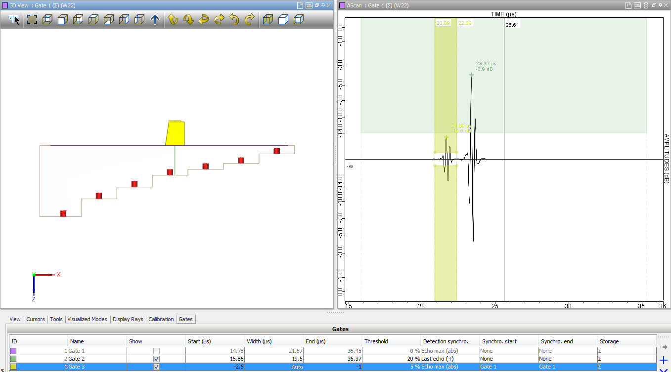
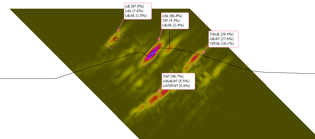
Acquisition gate definition / Mode identification tool
A ray tracer completes these tools (it takes into account mode conversion, reflections, displays time of flight, etc.). This tool is connected to the list of modes, and helps in understanding different interactions. All results can be exported in ASCII files (A-Scan, C-Scan, POD curve, etc.).
In addition to simulation results, CIVA can import and post-process real acquisition data files coming from EddyFi systems ("M2M" brand: Gekko, Panther, MultiX), Olympus (opd, oud, rtd et format odat X3), Prelude and TFM from TPAC, or Zetec data previously exported in text. Therefore, the simulation software benefits from all the features available in the UT analysis tool: analyze your simulations as you do for real acquisitions thanks to CIVA UT Analysis!