
Guided Wave Testing with CIVA
Simulation capabilities for Guided Waves include the propagation of ultrasonic beams in planar and tubular waveguides or more complex geometries and their interaction with defects.
Probes
A wide range of UT probes, standard and advanced designs can be handled:
- Piezo electric-like Transducer with or without wedge, Magnetostrictive-like probes or EMAT probes (involves a coupling with CIVA ET)
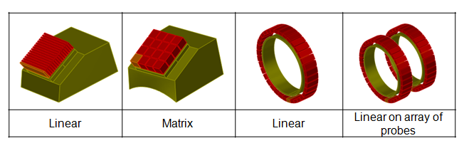
- Single element or phased-array probes (see Phased Arrays section)
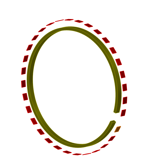
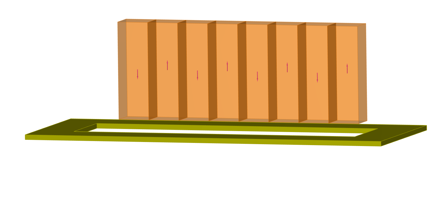
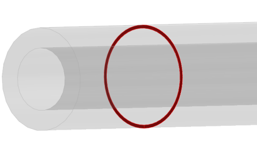
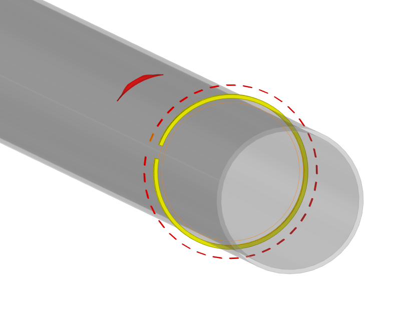
- Encircling or encircled probes for pipe inspection
- Different types of solicitations (shear or longitudinal vibration)
- Different configurations (Pulse-Echo, Pitch-Catch transmission or Pitch-Catch reflection)
Specimens
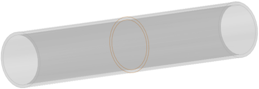
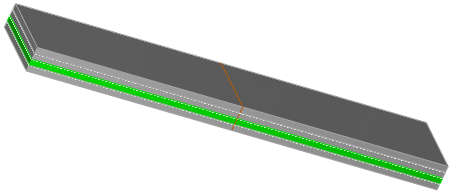
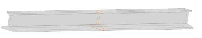
Planar structures, pipe-like structures (with possibly some discontinuities), and parts having 2D CAD cross section, such as rails, are considered for guiding waves by CIVA. The specimen may be homogeneous or heterogeneous, taking into account a coating for example. Each medium should be isotropic and attenuation laws may be considered. This is also possible to account for pipes filled with fluid. Buried pipes can be considered in the mode computation module.
Fluid or solid surrounding media around the test component can be taken into account in mode and field computation tools for a more accurate modeling of buried and immersed components in guided wave simulation. If the fluid medium is defined as a layer between two solid parts, this modelling process can even be defined in the Inspection Simulation module (i.e. defect/discontinuity response).
Anisotropic materials (such as CRFP-like composites) can be considered in the mode computation module.
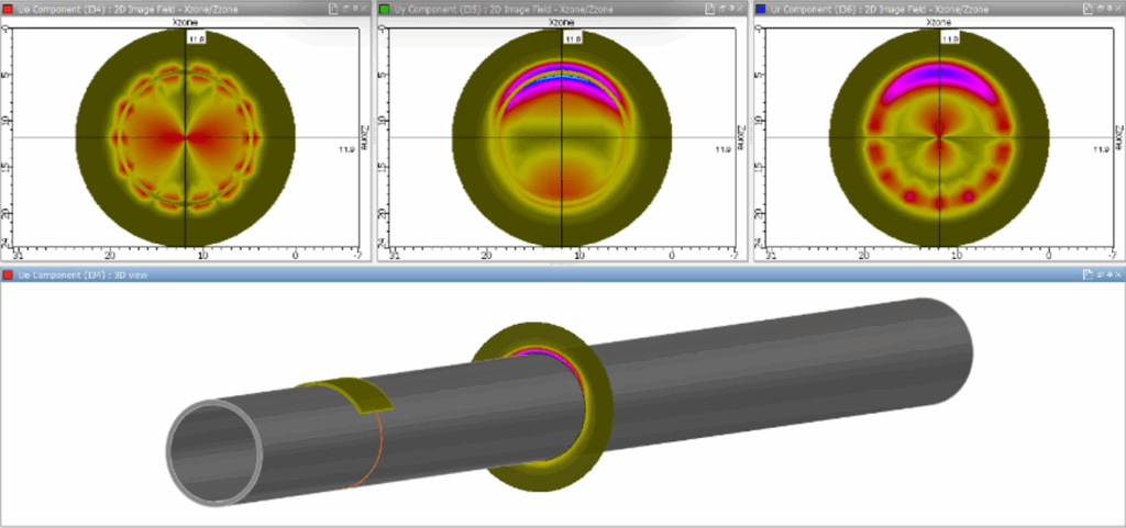
Phased-Arrays Settings
CIVA allows defining delay laws on different kinds of probes: linear arrays on plates, encircling or matrix arrays on pipes:
- Independent definition of emitting or receiving elements
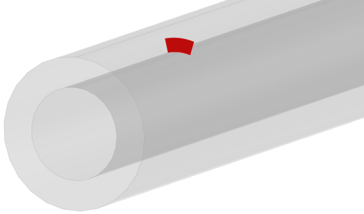
Phased-array probe accounted for by CIVA
In the case of pipes, CIVA GWT allows the user to compute delay laws in order to focus on a given point of the pipe, as long as the excitation frequency is lower than the cut-off frequency of mode L(0,3).
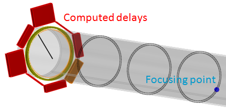
Visualization of delay laws in CIVA GWT
Flaws
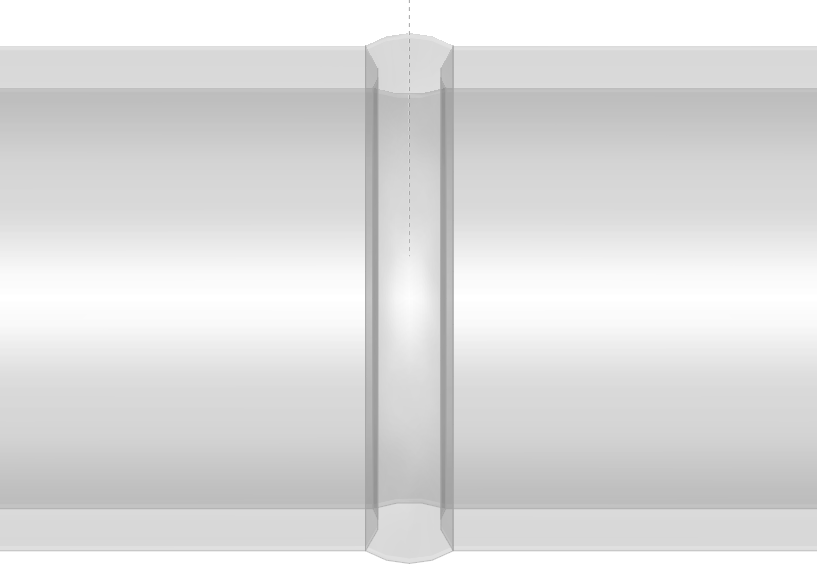
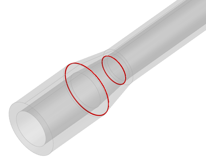
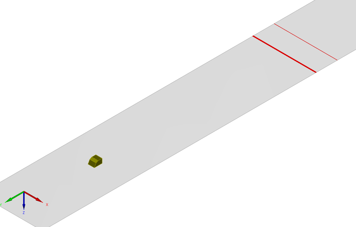
In CIVA GWT, 2D geometrical discontinuities, such as a weld, a groove, a transition (varying diameter) or a junction between straight parts, can be handled for echoes prediction.
In simple plates or with such types of 2D discontinuity, one or several groups of defects (axisymmetrical or with infinite extension in plates) can be accounted for. They can be without thickness like a crack, volumetric with a rectangular or semi-elliptical section, or a solid inclusion.
In tubes, CIVA GWT can model circumferential cracks with parametrized angular apertures.
Through a 3D FEM computation zone, CIVA GWT is also able to compute defect responses from 2D CAD specimens and tubes with planar or volumetric flaws (including solid inclusions) through a 3D FEM computation zone.

Results
Modes computation
A first module computes the dispersion curves associated to the specimen in a given frequency range.
Modal displacements and constraints are computed for each mode at each frequency of the frequencies range.
- Application: selection of the working frequency range and visualization of the properties of the modes selected for the testing
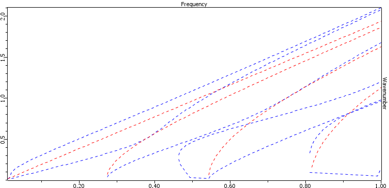
Dispersion curves in CIVA GWT
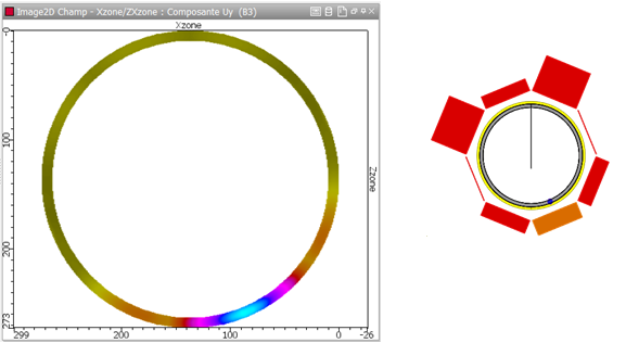
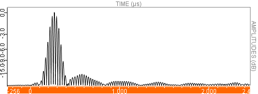
Field computation
A second module allows simulating the ultrasonic beam radiated in different cross-sections of the specimen. The modal repartition of the emitted energy is displayed versus the frequency in the bandwidth of the probe. The displacement and constraints are determined in a time range, which allows visualization of the transit of the different waves at each cross-section or the verification of the focusing allowed by a delay law.
- Application: design of specific probes dedicated to Guided Waves inspection, optimization of the ability for a sensor to select a given mode, or verification of the focusing allowed by a given delay law
 <
<
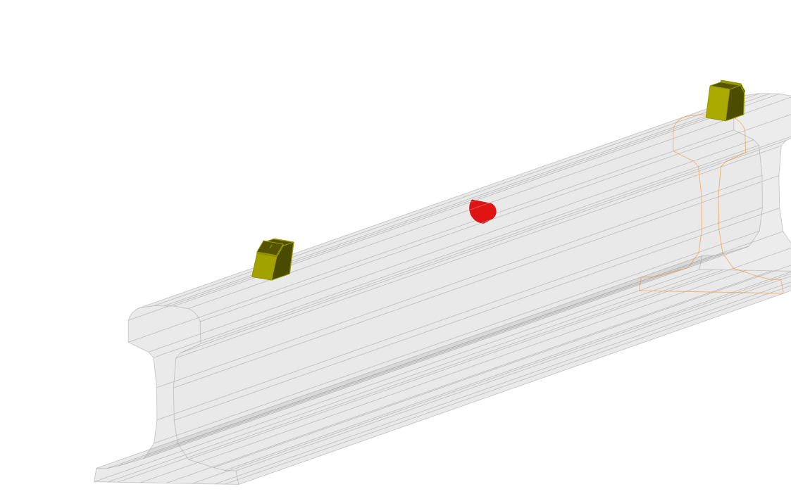
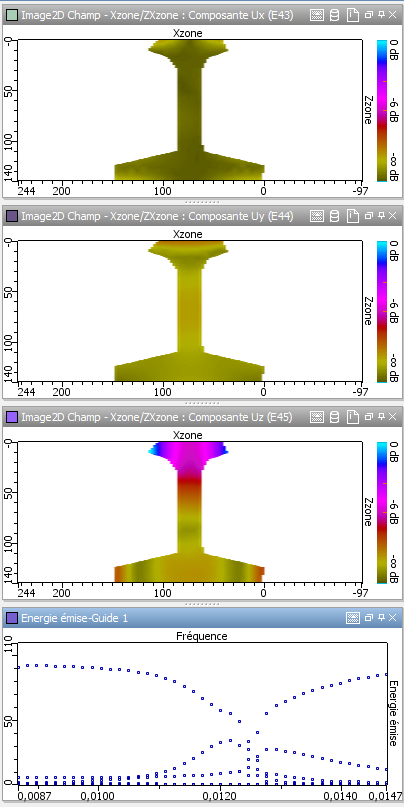
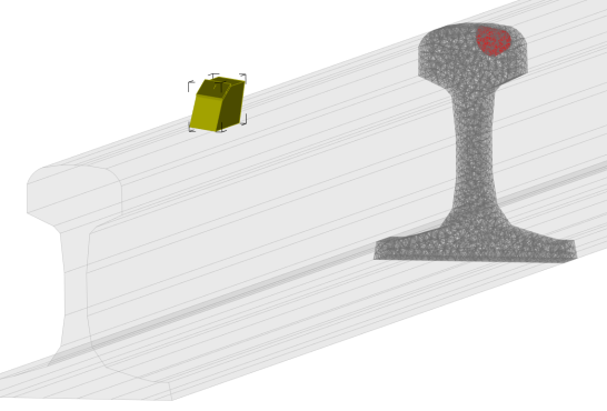
Beam computations in CIVA GWT:
Left: Railway track; Center and Right: Beam focusing and corresponding delay law visualization;
Bottom: Buried pipe beam computation
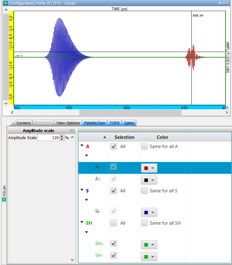
Defect response
This module simulates the beam/flaw interaction (or beam/geometrical discontinuity) and predicts the amplitude, waveform and time of flight of the different types of echoes: incident, reflected and mode converted.
A mode identification tool is available to analyze the modes involved in the obtained A-Scan.
- Application: simulation of a complete Guided Waves testing
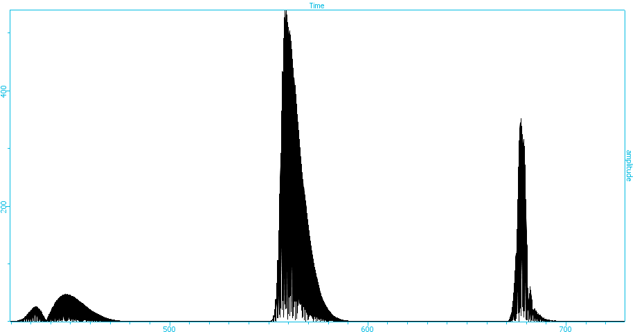
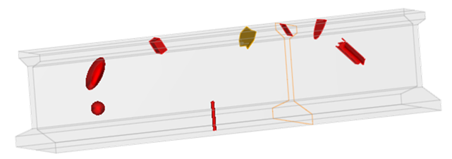
Mode identification on an A-Scan
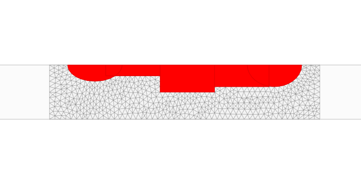
A-scan obtained on a flawed 2D CAD (railway track)
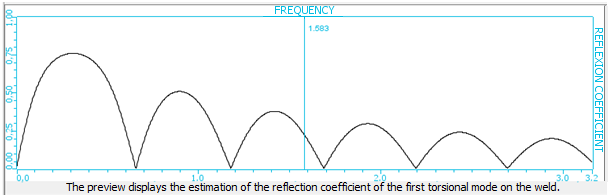
On a weld, a preview helps the user to estimate the reflection coefficient of the first torsional mode on the weld, depending on the excitation frequency.
To understand and quantify the impact of influential parameters on a NDT inspection, parametric studies in CIVA are particularly adapted since it is easy and fast to precisely change and monitor parameters. Based on a first set of computations, metamodels can also be calculated in CIVA, which provides extensive new results to the user in real time, as well as powerful analysis tools, such as multi parametric analysis and sensitivity analysis to evaluate the relative impact of influential parameters.
POD calculations (Probability Of Detection) are available, based on the accounting of uncertain input parameters. Single or Array of POD curves can be plotted inside CIVA.