
CIVA-ATHENA2D, SA-FE hybrid approach for Ultrasounds
Summary
 The ease of use of CIVA, the power of finite elements… But fast!
CIVA-ATHENA2D is an “add-on” module available with CIVA UT . This tool consists in a hybrid module, using both conventional semi-analytical methods of CIVA and the FEM code ATHENA (from EDF). The connection with Finite Elements allows taking into account more complex phenomena that can occur in a UT inspection.
The FE box
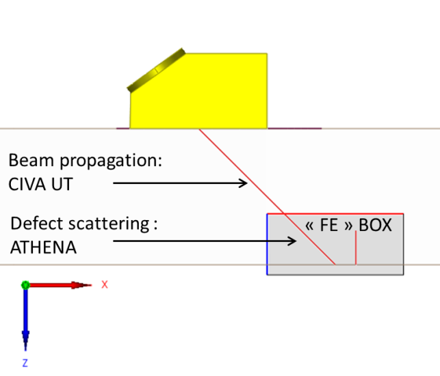
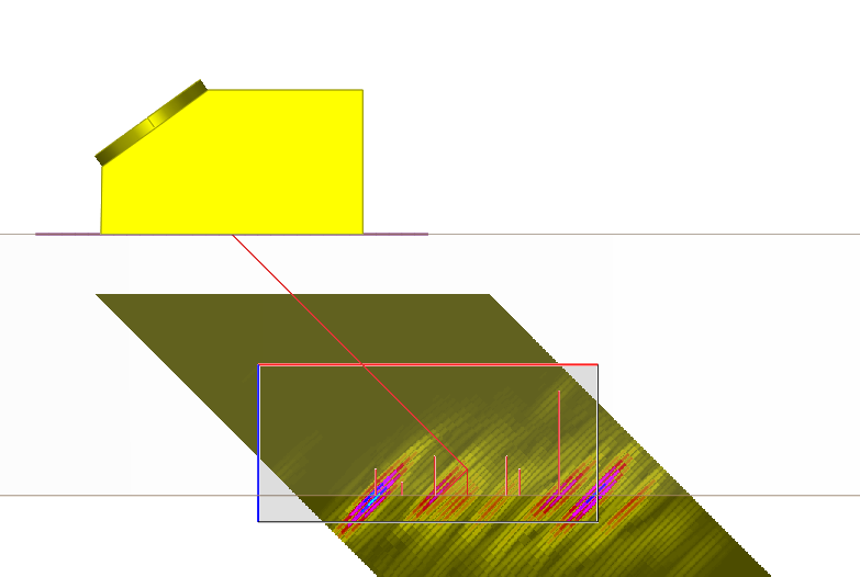
CIVA-ATHENA2D coupling illustration
In CIVA-ATHENA2D, a finite element rectangular box is defined. Out of this box, the UT beam propagation is modeled with the conventional CIVA semi-analytical pencil method. In the box, calculation is made by FEM using the incident beam calculated on the box boundaries as an input. Typically, FEM will be used to simulate UT beam / defect interactions (and beam / geometry interactions) whereas the fast semi-analytic model is used to simulate the round trip propagation of ultrasounds from the transducer.
Simulation examples: Take into account all phenomena
The interest of CIVA-ATHENA2D is to account for all physical phenomena in the beam / defect interaction:
- Accounts for creeping waves and Rayleigh waves generated on flaws
- Simulates multiple scattering by flaws
- Precisely calculates the response from small flaws with respect to the wavelength
- Computes interface echoes
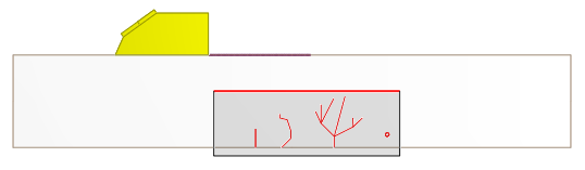
Left: Network of flaws (multiple scattering)
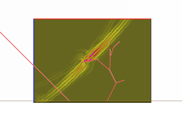
Right: Complex flaws and creeping waves generated
These possibilities allow precisely simulation of the response from clusters of flaws or from complex flaw profiles accounting for multiple reflections and the generated surface waves.
Specimen
Even if 3D effects are ignored, no restriction is made on the available components in the user interface compared to CIVA UT. As this is a 2D module, to give quantitative results, the user shall consider component geometries that can be locally considered as 2D, or at least that make sense in 2D.
Probes
As this is a 2D code, only a 2D section of the transducer is modeled. But no restriction is made in the transducers available in the user interface.
User will pay attention to the defined transducer (in terms of focusing or crystal shape) so that the 2D simulation makes sense.
The scanning of the probe will be in the incident plane only as the 2D box is fixed in this plane.
Tandem configurations are allowed but only make sense if the incident and reflected beam at the box boundary is a direct beam for both the transmitter and emitter.
TOFD configurations are also available but only with a scanning in the incidence plane.
Phased-Array Settings
The phased array settings of CIVA UT are available in CIVA-ATHENA2D, the calculation can be done for one or several shots.
Flaws
The flaws that can be defined by their 2D cross-section are available: Planar, multifaceted, branched, and Side Drilled Holes.
Flaws available (including complex profiles)
Results: Visualize beam / defect scattering
In addition to the classical curves and images already available in CIVA UT (A-scans, B-scans, 3D view, reconstructed view, etc.), CIVA-ATHENA2D allows visualizing defect scattering phenomena by displaying snapshots of the beam in the FEM zone (maximum amplitude, or propagation versus time and video).
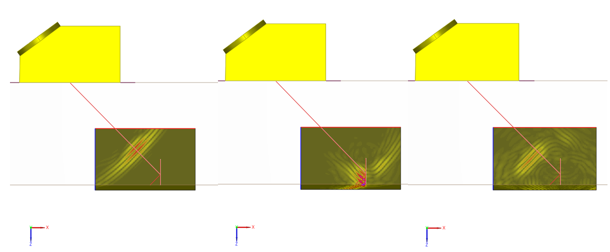
Snapshots of the beam / flaw interaction VS time
Simulation remains easy and fast
In addition to its advanced capabilities, the coupling between CIVA and ATHENA has other advantages: the computation is faster than a complete Finite Element computation, while all phenomena are accounted for regarding the beam / defect interactions. The configuration is defined in the “user-friendly” CIVA interface, with very few specific parameters for the FEM calculation. Therefore, CIVA-ATHENA2D is easy to use.
CIVA-ATHENA2D… Is a 2D module
CIVA-ATHENA2D uses a 2D beam computation and a 2D FEM calculation from ATHENA. Therefore, 3D effects are intrinsically ignored, while it gives very precise results as soon as the hypothesis can be credited, which mainly means:
- Considering only flaws that can be defined by their 2D cross-section: planar notches, multifaceted or branched flaws and Side Drilled Holes
- Comparing flaws response independently from their extension in the orthogonal plane: same extension and at the same depth, or extension larger than the beam width
- Component geometries that can be locally considered as 2D
Besides 2D configurations, using CIVA-ATHENA2D remains interesting for qualitative analysis.