AUT Pipeline testing with CIVA
What is CIVA AUT Pipeline?
For Oil & Gas offshore and onshore projects, pipeline girth weld integrity is mainly verified thanks to dedicated Phased Array UT systems. Governed by DNV-ST-F101 standards and DNV-RP-F118 recommended practices, inspection techniques require proper performance demonstration tests. This new dedicated simulation tool, relying on the recognized and powerful CIVA simulation technologies, has been designed for Oil & Gas stakeholders to support pipeline project validation as well as to optimize inspection performance and reliability.
CIVA AUT Pipeline includes 2 ranges of tools:
- A dedicated set of modules allows you to quickly enter the project parameters and guides you through the different steps one after the other:
- AUT Calibration: Run channel calibration
- AUT Sensitivity: Define a range of variables for essential parameters
- AUT Sizing: Evaluate sizing accuracy
- AUT POD: Compute Probability Of Detection versus flaw size
- The “generic” Beam Computation, Sensitivity coverage and Inspection simulation tools of CIVA UT are also available in CIVA AUT Pipeline for girth weld modelling
CIVA AUT Pipeline can address Zonal Discrimination (ZDM) and Total Focusing (TFM) Methods.
In the AUT Calibration module, define the specimen, channels and reference defects:
Specimen
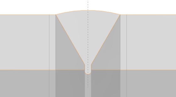
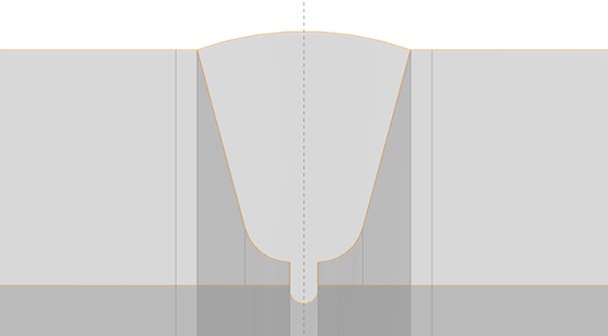
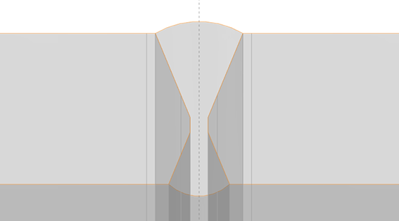
- Girth weld geometries defined with parameters
- J (U), V or X bevels shape
- Made of isotropic homogeneous materials
Probe
- Contact linear PA or single element probes
Channels
- FILL, HOT PASS and VOLUME channels with orientated FBH reflectors
- ROOT, CAP (and CROSS for TFM) channels with planar rectangular reflectors
- In ZDM, you can import any focal laws previously set (for instance in CIVA “generic modules”)
- Full Matrix Capture for TFM
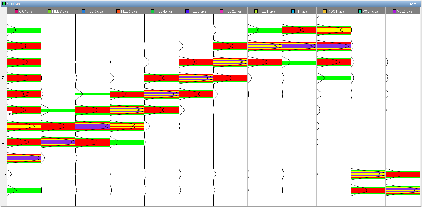
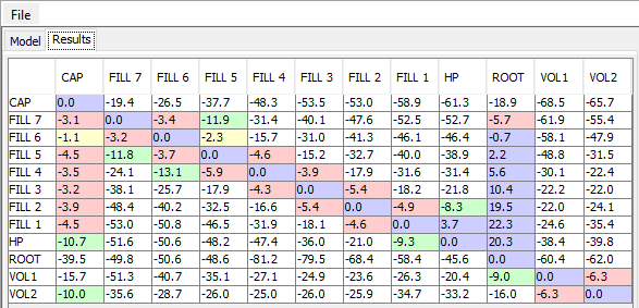
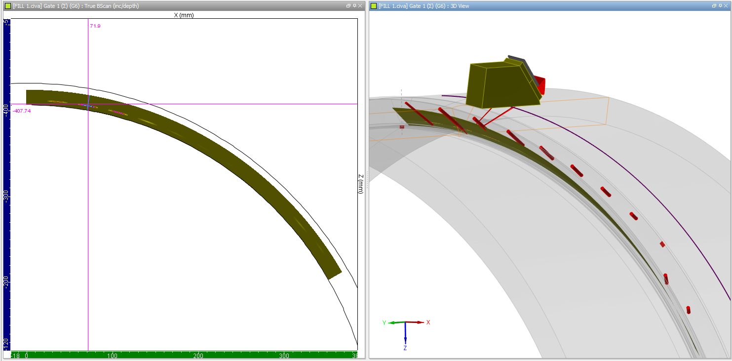
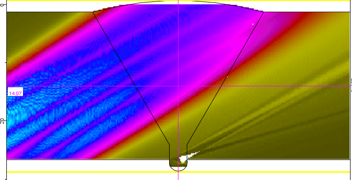
AUT Calibration provides the response of calibration reflectors (strip chart, tables of amplitude, but also B-Scan view) and zone coverage images:
In the AUT Sensitivity module, define variable parameters and study its impact on the target flaw modelled by a planar rectangular flaw:
Essential variable parameters
- Pipe Thickness
- Probe standoff
- Waves velocity
- Target flaw length
- Target flaw height
- Target flaw depth
- Bevel angle (i.e., target flaw tilt angle)
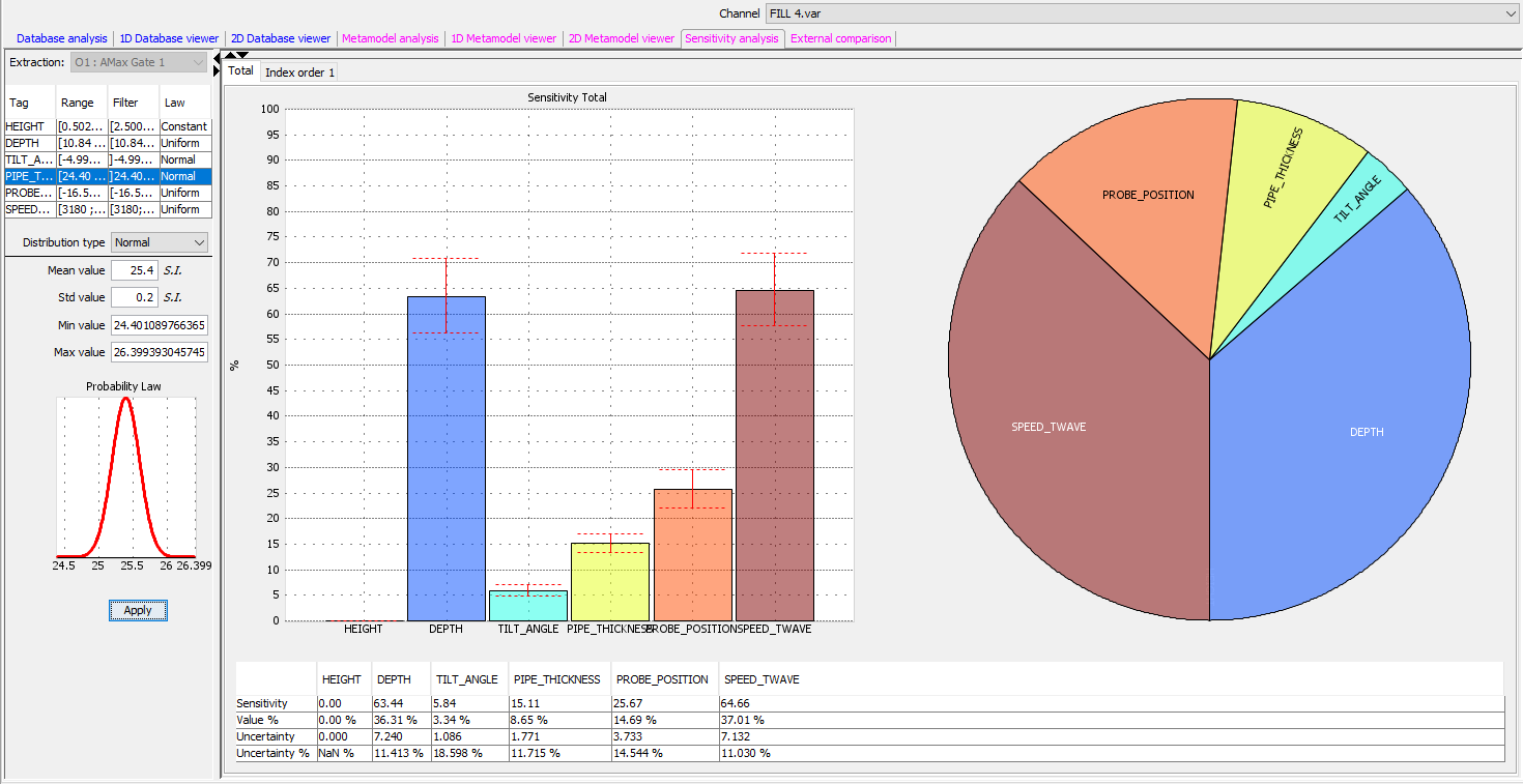
AUT Sensitivity provides a sensitivity analysis for all channels, based on the variation ranges defined for the essential parameters and the number of simulated cases. A metamodel is generated from the simulations performed to enhance the data set sampling and allows to investigate in real-time many different inspection scenarios (essential parameters variability can be changed).
Different plots are available:
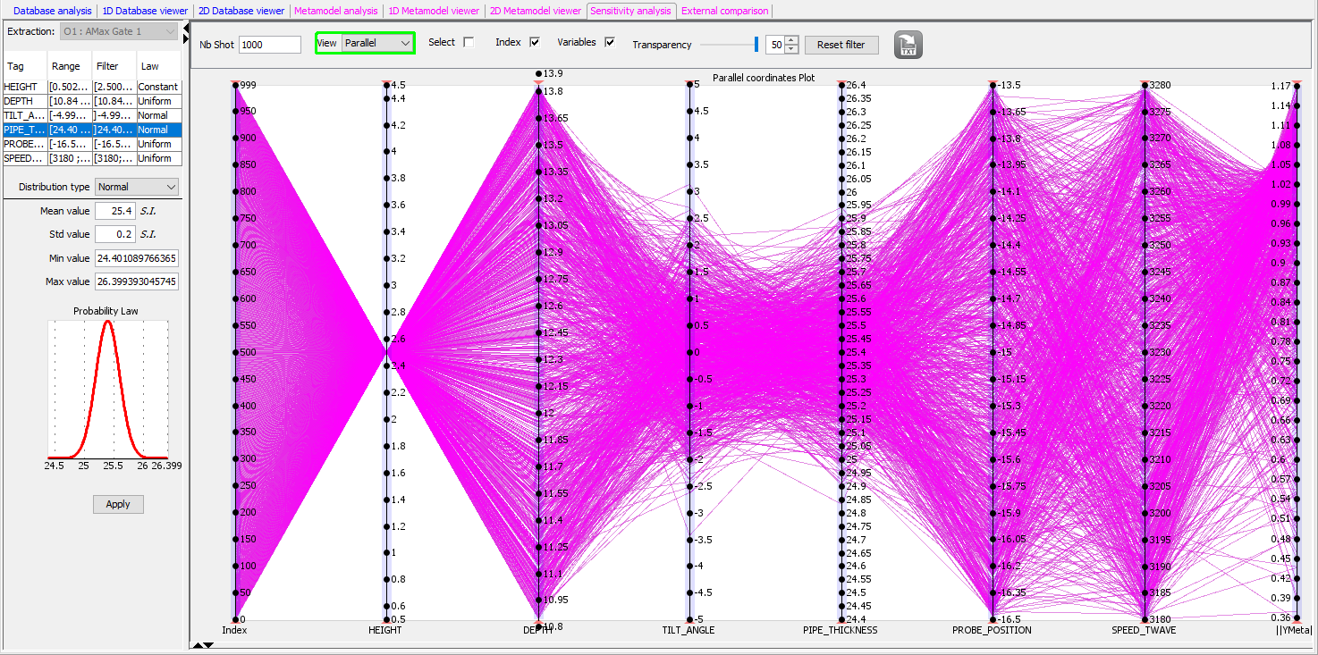
- Parallel plot of the simulated database
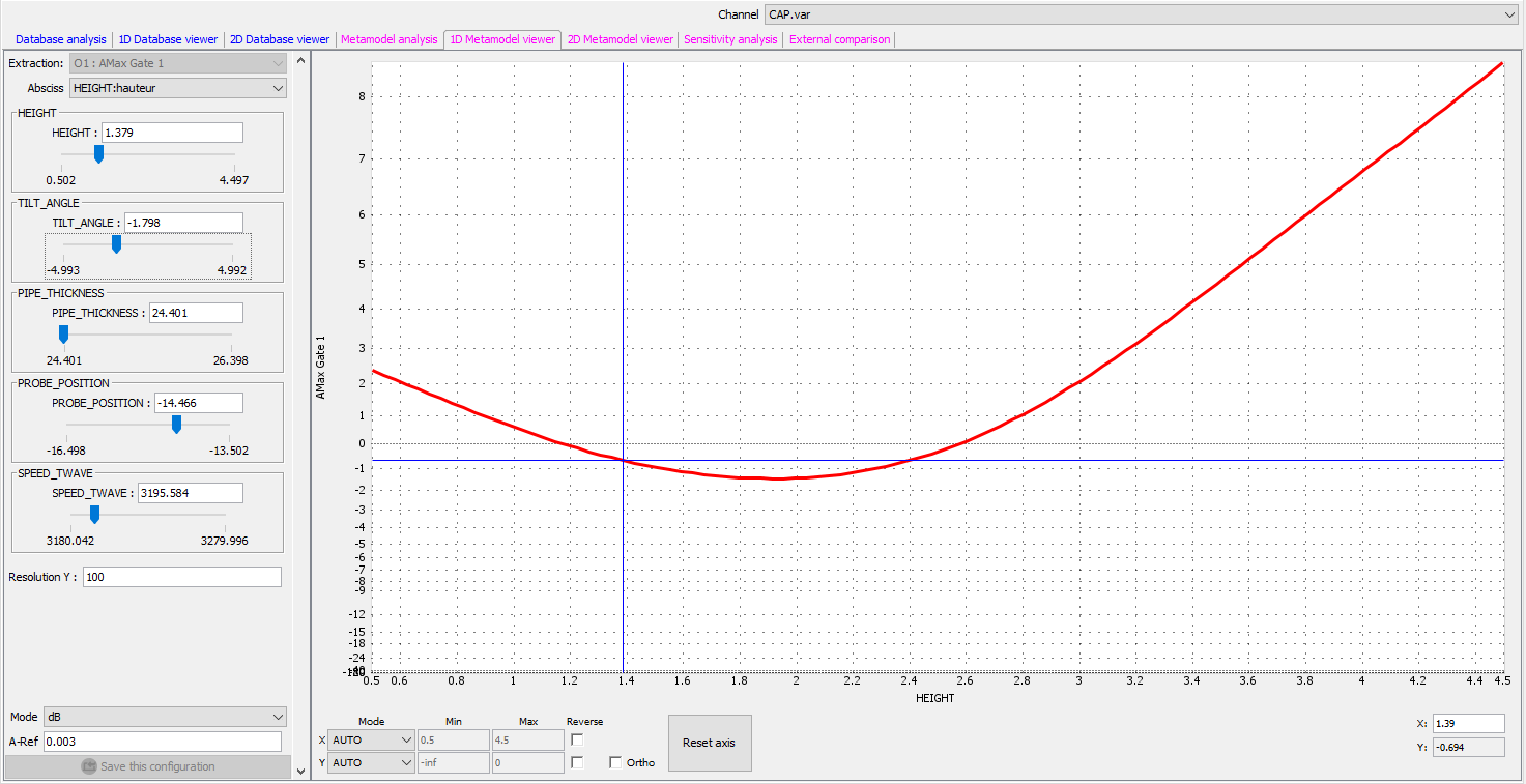
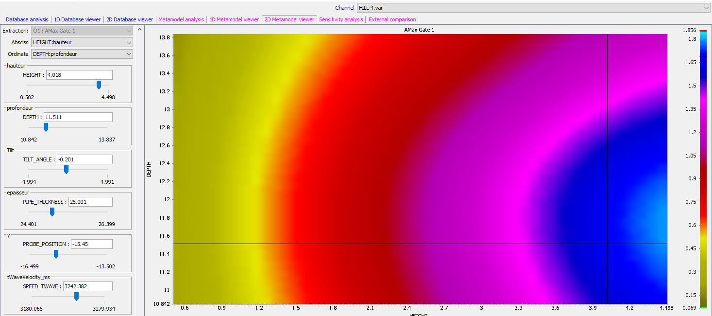
- 1D-Curve or 2D-Maps of parameters impact on the signal amplitude based on the metamodel
- Parallel plot of the metamodel
- Sobol indices that rank parameters influence
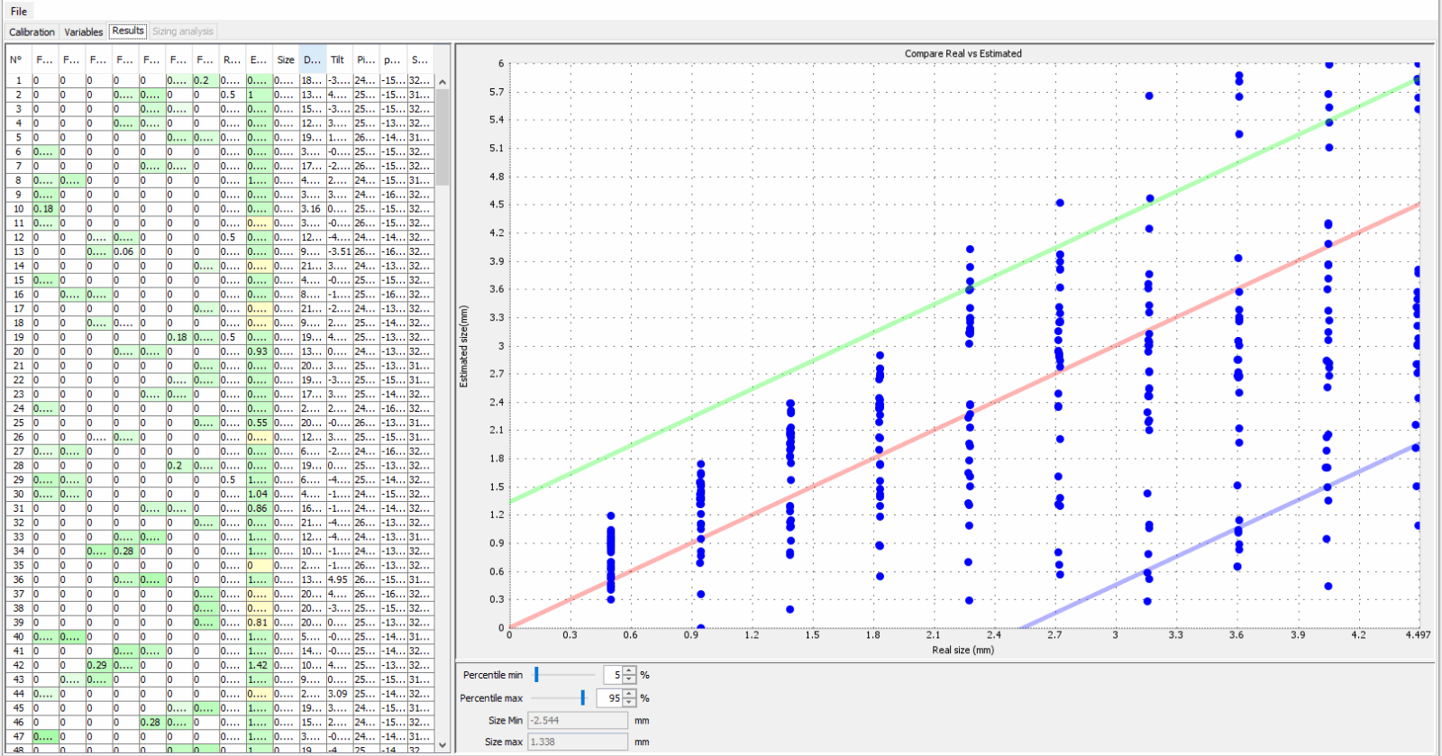
From the AUT Sensitivity results, you can enable AUT Sizing module that will evaluate the sizing accuracy, display true vs predicted flaw size graph and associated under / oversizing limit percentiles, and estimate which parameters influence sizing errors.
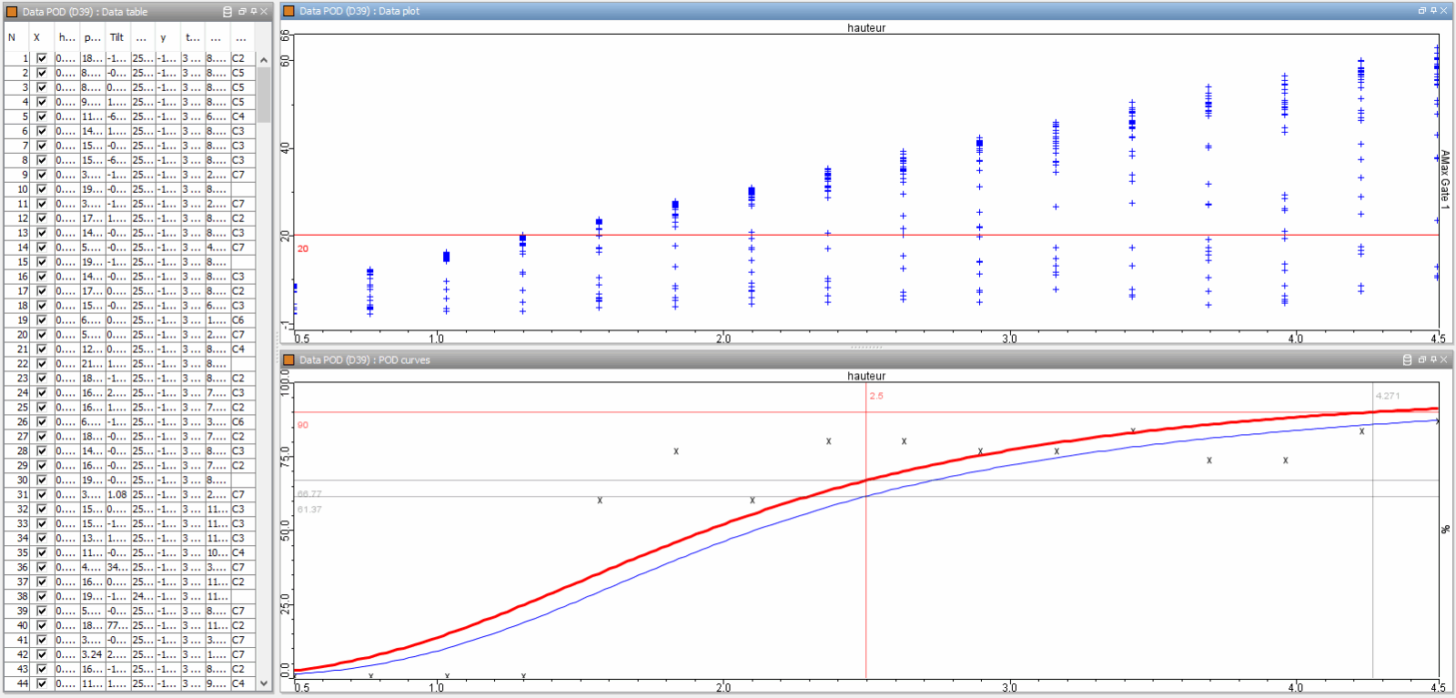
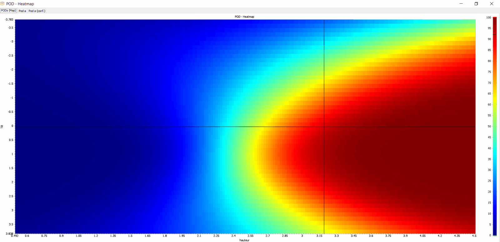
From the AUT Sensitivity results, you can also enable AUT POD module, that will compute POD curves (Probability Of Detection versus flaw size) for one or several channels, beam of POD curves, 2D Heatmaps, and check which parameters degrade (or could optimize) POD.