Eddyfi is a young company from Quebec that was founded in 2009 by executives from the field of Non Destructive Testing. It develops and sells non-destructive multi-element eddy current monitoring equipment among other things, to measure and detect defects such as loss of thickness, stress corrosion or stress cracking or pitting, porosity, inclusions. One of their probe, the I-Flex probe, designed specifically for the inspection of complex geometries, has been modeled in CIVA 2016. This study aims to evaluate the predictions of CIVA in the framework of simulation of defects inspections with this Eddyfi probe.
specimen
The acquisitions are made on the LCME93 N ° 1 mock-up, which is a plate in Inconel 600.
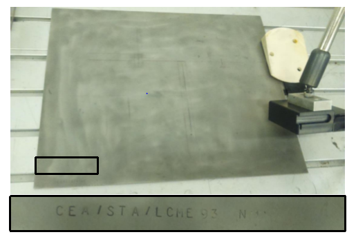
LCME 93 N°1 mock-up
In CIVA the plate is modeled by a plane and homogeneous geometry of length L = 300 mm, width l = 244 mm and height h = 1.55 mm. The material is Inconel 600, the conductivity is 1.02 MS.m - 1 and the relative permeability is 1.
defects
In the inspected plate, 15 defects have been machined, including 5 large notches, 5 small notches and 5 holes of 2 mm diameter, arranged as shown on the figure below:
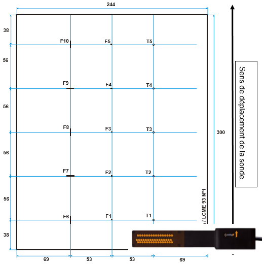 Disposition of defects in the LCME 93 model No. 1 and visualization of the direction of movement of the probe.
The study published on this page only deals with the characterization of the hole response. All the geometric characteristics of these flat bottom holes are gathered in the table below:
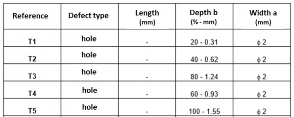 Hole dimensions of the LCME 93 plate N ° 1.
In CIVA, the piece and the flat bottom holes are modeled like this:
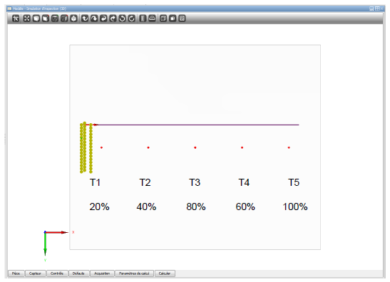 Simulation of T1 to T5 flat bottom holes of the LCME 93 plate N ° 1..
probe
Experimental acquisitions are carried out with Eddyfi's Industrial and Phased Array I-Flex "ECA-IFG-056-250-048N03S", which offers great flexibility for the inspection of smooth surfaces that can be curved. The probe winding consists of 48 coils arranged in 3 rows of 16 coils. The probe is controlled by the Ectane 2 acquisition system with Magnifi software.
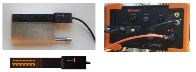
The Eddyfi IFlex ECA-IFG-056-250-048-N03S and the Ectane 2 Eddyfi acquisition system
The geometric parameters of the probe are summarized in the table below, where a and b are the distances between the rows of coils as shown in the figure below:
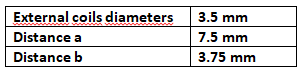
Geometric parameters of the I-Flex probe
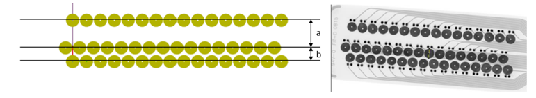
Positioning of the 16x3 coils seen from the top of the probe (left) and radiography of the probe (right)
To model this type of probe in CIVA 2016, the winding is first defined by two coil networks, since the x-shift of the lines is not the same for all the lines.
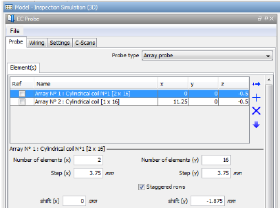
Winding definition of the I-Flex probe in CIVA 2016
acquisition
There are three acquisition modes of Eddyfi I-Flex multi-element probes, or topologies:
- Impedance, in absolute or differential mode
- The long single driver topology for which only one coil is used in transmission. This topology allows good performance for large or sub surface defects.
- The short double driver topology for which two coils are activated in transmission. This topology allows the detection of smaller defects thanks to smaller T/R distance and a quite high inducing field.
The Long Single Driver and Short Double Driver topologies each have a so-called "Axial" pattern, favoring the detection of axial crack type defects, as well as a "Transverse" mode favoring the detection of transverse or circumferential crack type defects. Experimental acquisitions are carried out for all modes of the probe with the exception of impedance mode.
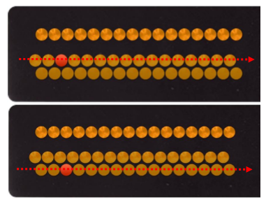
"Impedance" Topology, in absolute mode. Alternation of the two presented patterns.
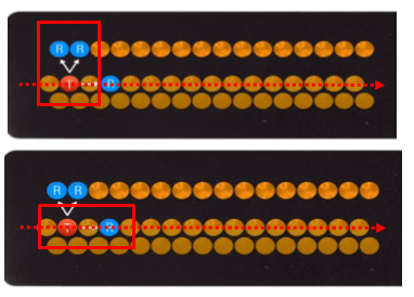
"Long Single Driver" Topology , in the red rectangle the "Axial" pattern at the top, "Transverse" at the bottom.
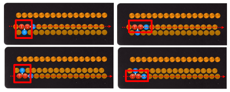
"Short Double Driver" Topology, in the red rectangle the "Axial" pattern on the left, "Transverse" on the right. Alternation of the two presented patterns.
Of course all the patterns of all topologies must be defined in CIVA. Below, two examples of single axial and double transverse driver topologies are presented.
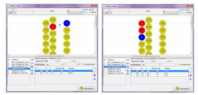
First pattern of the Long Single Driver Axial topology (left) and pattern of the Double Transverse Driver topology (right).
Experiment/simulation comparisons
The results of simulated and acquired data comparisons for flat-bottom holes T1 to T5 of the LCME 93 No. 1 plate are presented here for the 4 acquisition modes. They were all calibrated on the T4 flat bottom hole of the LCME 93 N1 plate. This hole has a diameter of 2 mm and a depth of 60%. The calibration value was chosen with an amplitude of 1V and an angle of 0 °. The simulations were carried out with a probe positioned in Y = 94.812 mm.
AXIAL LONG SINGLE DRIVER MODE
The following 3 figures show the results obtained for the axial single driver mode.
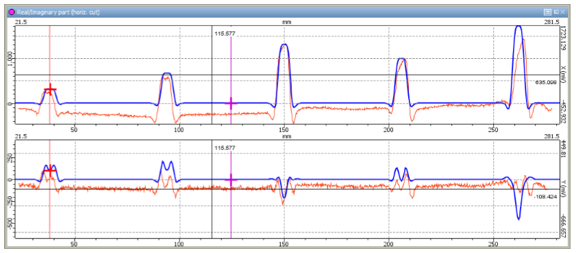
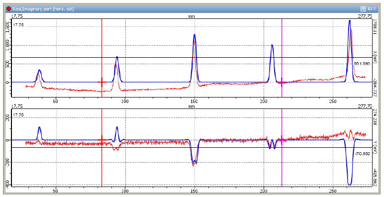
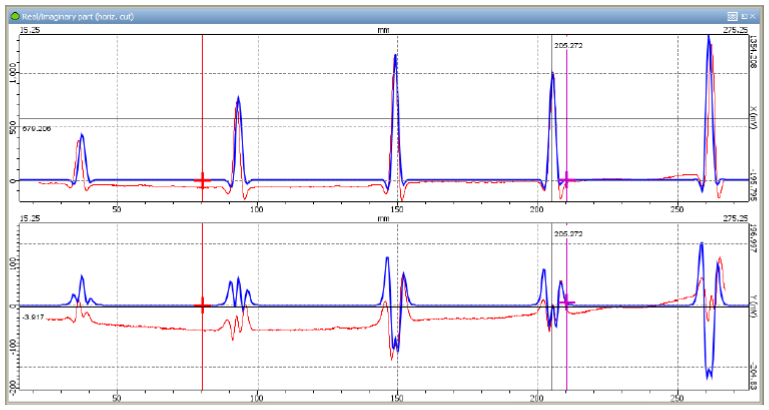
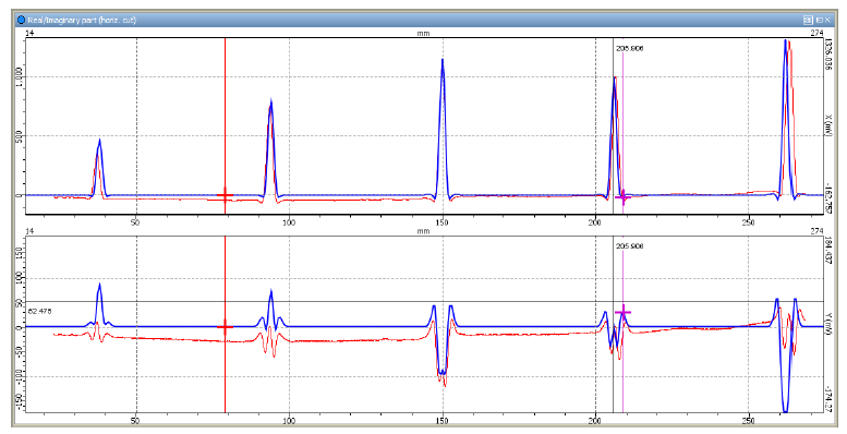
Real (X) and imaginary (Y) part of impedance for Axial Long Single Driver mode and flat bottom holes T1 to T5 of LCME 93 No.1 plate. In blue the CIVA simulation, in red the experimental acquisition.
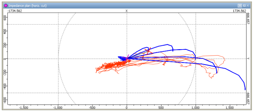
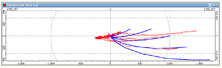
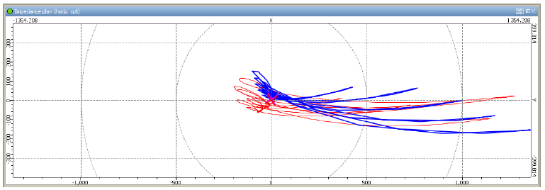
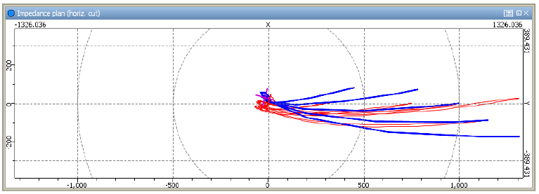
Impedance plan for the Axial Long Single Driver mode and the flat bottom holes T1 to T5 of the LCME 93 N ° 1 plate. In blue the CIVA simulation, in red the experimental acquisition.
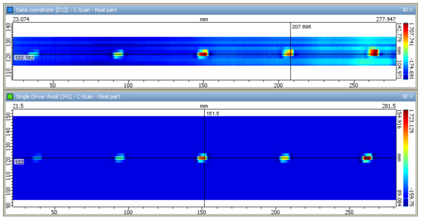
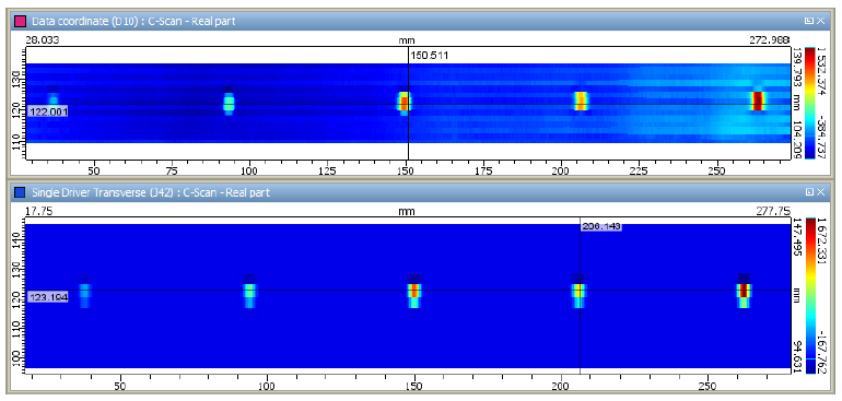
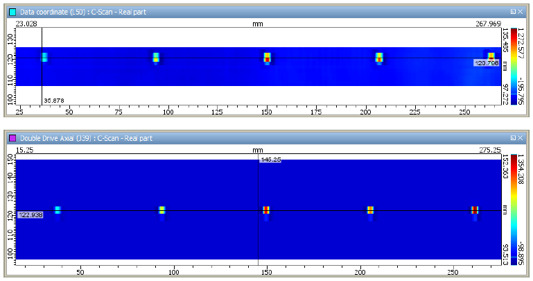
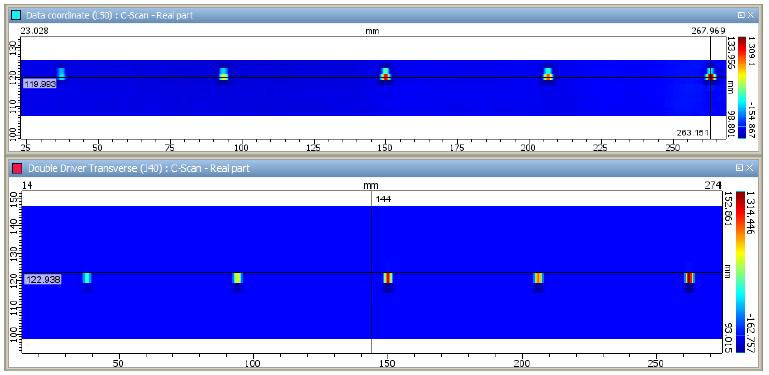
Cartography of the real impedance part for the Axial Long Single Driver mode and the flat bottom holes T1 to T5 of the LCME 93 N ° 1 plate. At the top the experimental acquisition, below the CIVA simulation.
The following table of results gathers all the results obtained on the flat bottom holes for the axial single driver mode.
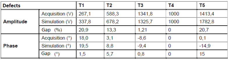
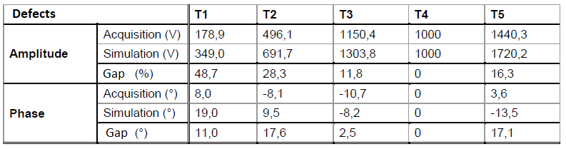
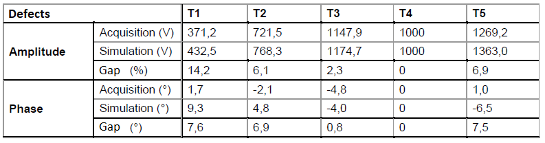
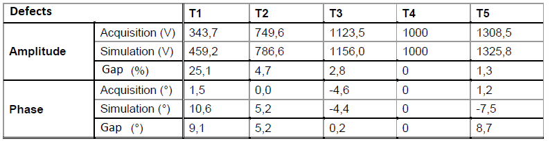
Amplitude and phase value measured in the impedance plane for the Axial Long Single Driver mode on flat bottom holes T1 to T5 of the LCME 93 No. 1 plate.
TRANSVERSE LONG SINGLE DRIVER MODE
The following 3 figures show the results obtained for the transverse single driver mode.
Real (X) and imaginary (Y) part of impedance for Transverse Single Driver mode and T1 to T5 flat bottom holes of LCME 93 No. 1 plate. In blue the CIVA simulation, in red the experimental acquisition.
Impedance Plan for theTransverse Long Single Driver Mode and Flat Bottom Holes T1 to T5 of the LCME 93 No. 1 Plate. In blue the CIVA simulation, in red the experimental acquisition.
Cartography of the real impedance part for the Transverse Long Single Driver mode and the T1 to T5 flat bottom holes of the LCME 93 No.1 plate. At the top the experimental acquisition, below the CIVA simulation.
The following table of results gathers all the results obtained on the flat bottom holes for the transverse single driver mode.
Amplitude and phase value measured in the impedance plane for Transverse Long Single Driver mode on flat bottom holes T1 to T5 of the LCME 93 No. 1 plate.
AXIAL SHORT DOUBLE DRIVER MODE
The following 3 figures show the results obtained for the axial short dual driver mode.
Real (X) and imaginary (Y) part of the impedance for the Axial Short Double Driver mode and the flat bottom holes T1 to T5 of the LCME 93 No.1 plate. In blue the CIVA simulation, in red the experimental acquisition.
Impedance plan for the Axial Short Double Driver mode and the T1 to T5 flat bottom holes of the LCME 93 N ° 1 plate. In blue the CIVA simulation, in red the experimental acquisition.
Cartographie of the real impedance part for the Axial Short Double Driver mode and the T1 to T5 flat bottom holes of the LCME 93 N ° 1 plate. At the top the experimental acquisition, below the CIVA simulation.
The following table of results gathers all the results obtained on the flat bottom holes for the axial short double driver mode.
Amplitude and phase value measured in the impedance plan for the Axial Short Double Driver mode on flat bottom holes T1 to T5 of the LCME 93 No. 1 plate.
TRANSVERSE SHORT DOUBLE DRIVER MODE
The following 3 figures show the results obtained for transverse short double driver mode.
Real (X) and imaginary (Y) part of the impedance for the Transverse Short Double Driver mode and the T1 to T5 flat bottom holes of the LCME 93 No.1 plate. In blue the CIVA simulation, in red the experimental acquisition.
Impedance plan for the Transverse Short Double Driver mode and T1 to T5 flat bottom holes of the LCME 93 N ° 1 plate. In blue the CIVA simulation, in red the experimental acquisition.
Cartography of the real impedance part for the Transverse Short Double Driver mode and T1 to T5 flat bottom holes of the LCME 93 N ° 1 plate. At the top the experimental acquisition, below the CIVA simulation.
The following table of results gathers all the results obtained on the flat bottom holes for the transverse short double driver mode.
Amplitude and phase value measured in the impedance plan for the Transverse Short Double Driver mode on flat bottom holes T1 to T5 of the LCME 93 No. 1 plate
ANALYSIS
As expected, the flat bottom holes are seen by the probe in axial or transverse mode as well. The results obtained experimentally and with CIVA are generally consistent.
For all modes we observe a strong drift from the baseline, which is probably due to the fact that the probe was not well plated on the specimen during acquisitions. This may explain the differences in magnitude observed in the tables. If we move apart this drift on the measurement, the signals obtained are close between simulation and experiment. The shape of the signals is coherent between acquisition and simulation outside the T5 flat-bottomed hole. Indeed, a large gap persists on the imaginary part of the impedance of this flat-bottomed hole through T5 regardless of the acquisition mode of the probe. This may come from a non-optimal VIM model in CIVA for large through wall holes and would need to be investigated. Despite this difference in the shape signal, the consistency of the results on this T5 hole remains very good in terms of ampitude and phase.
Back to TILTED COIL
Back to FLAT SPECIMEN