
Inclusion in water – single element – Experimental set-up
Summary
- Probes and refLEctors used
- Realized measures
- Cartographies IN XZ and YZ PLANes and profile according to Z
- Cartographies in the XY plan
- CHARACTERISTICS OF ECHOES SPECTRUM
- DETERMINING PROBE / REFLECTOR DISTANCE during ACQUISITIONS
- Adjustment of the probe orientation
- REPRODUCIBILITY AND EXPERIMENTAL UNCERTAINTY
- EFFECT OF the ANTI rust ADDITIVE IN WATER
Probes and refLEctors used
Beams in water from 3 diffrent probes have been studied:
- Flat probe Ø6.35mm, 2.25MHz.
- Flat probe Ø6.35mm, 5MHz.
- Focused probe Ø9.5mm, 10MHz.
Four stainless steel inclusions of diameter 1, 2, 4, and 6 mm and an infinite plan have been used as reflectors.
Realized measures
Cartographies IN XZ and YZ PLANes and profile according to Z
For each probe, cartographies in XZ and YZ plans have been recorded for the 4 inclusions. A profile along Z is acquired for the infinite plan (see axes of Figure 1). Acquisition examples are presented on Figure 1 and Figure 2.
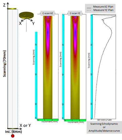
Figure 1 : Examples of experimental cartographies XZ and YZ, case of the Ø2mm diameter inclusion. Flat probe Ø6.35mm, 2.25MHz.
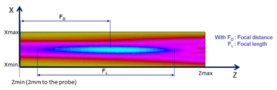
Figure 2 : Measure of the distance and of the focal length.
Cartographies in the XY plan
Cartographies in the plans XY were also recorded for the inclusion located at the distance « Z » from the probe for which the amplitude trasmitted along its axis is maximum (Figure 3).
An example of this kind of cartography is presented on Figure 4 (5MHz flat probe).
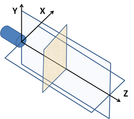
Figure 3 : Scheme of the cartographies in the plans XY at diffrent distances Z from the probe.
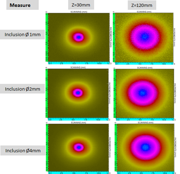
Figure 4 : Examples of experimental XY cartographies. Flat probe Ø6.35mm, 5MHz.
CHARACTERISTICS OF ECHOES SPECTRUM
The spectrum of the echo of an infinite plan is often used to determine the central frequency and bandwidth of the probe. These variables were measured from experimental echoes and compared with those predicted by CIVA. These comparisons were also realized from the inclusions spectra.
In the following:
- we’ll call “amplitude / distance” curve the ecodynamic curve showing the evolution of the maximum amplitude of the echo of a reflector as a function of its distance from the probe as it moves away along the probe axis (these are XZ or YZ curves).
- we”ll call “XY curve” the ecodynamic curve that shows the evolution of the maximum amplitude of the echo as a function of its distance from the central axis of the probe as it moves away from this axis at a constant Z.
DETERMINING PROBE / REFLECTOR DISTANCE during ACQUISITIONS
The procedure for determining this distance is:
- The reflector (flat or inclusion) is placed far enough from the probe so that its echo is temporally resolved.
- The time of flight “t” of the envelope of the echo is measured.
- The distance “d” between the probe and reflector is derived from the formula d = (vL * t) / 2 (the speed “vL” of the he wave propagation in water was measured using rebound multiple echoes on a infinite flat reflector : vLwater = 1483 ms-1).
In the example of the 10 MHz focused probe presented in Figure 5, the time of flight of the echo of the Ø1mm inclusion is 25.79μs, the distance deduced between the probe and the inclusion is 19.1mm.
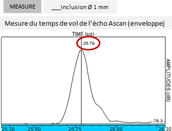
Figure 5 : Example of calculation of the probe / inclusion distance specified in the experimental files. Case of the Ø1mm inclusion, 10MHz focused probe.
Adjustment of the probe orientation
To achieve a beam cartography, the transducer must be finely oriented so that the beam axis is perpendicular to the XY plan formed by the displacement axes of the probe.
The experimental setup for inclusion is shown on Figure 6. The procedure allowing to precisely adjust the orientation of the probe consists in a systematic checking of the symmetry of the inclusion echo along the X and Y axes (Figure 7 ). The orientation correction is provided by a goniometer disposed on the transducer support.
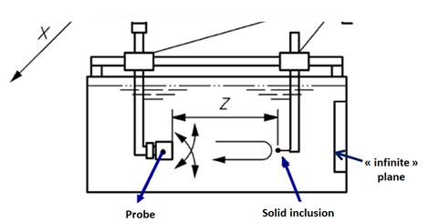
Figure 6 : Set-up for measuring the characteristics of the ultrasonic field radiated by an immersion probe in pulse echo.
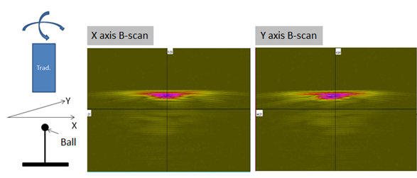
Figure 7 : Checking the orientation of the probe relative to the mechanical axes of movement.
In the case of the infinite plan, the effect of a the probe disorientation on the amplitude of the echo of infinite plan was evaluated by performing five measures: one with non disoriented probe (0 °) and four with disorientation + 1 °, 1 °, 2 ° and -2 °. The superposition of the amplitude / distance curves obtained with these different orientations (Figure 8) shows the significant effect of disorientation on the amplitude. This effect decreases when the water path rises. The comparison of measurements at 0 ° and +/- 1 ° ensures the “0 °” orientation of the probe.
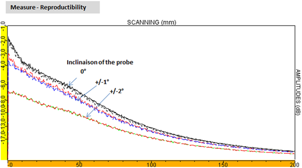
Figure 8 : Experimental results, amplitude/distance curves obtained for the infinite plan and different incidence angles of the probe (0 °, + 1 °, 1 °, 2 ° and -2 °). These curves are used to verify the orientation of the probe relatively to the plan. Ø6.35mm flat probe, 5MHz.
REPRODUCIBILITY AND EXPERIMENTAL UNCERTAINTY
The experimental uncertainty associated with mechanical adjustments evaluated by disassembly and reassembly of the complete device is 1dB. The confidence interval of the experimental data has been estimated at +/- 2 dB (1dB linked to uncertainty on reflector studied and for 1dB related to the reference reflector for the amplitudes).
EFFECT OF the ANTI rust ADDITIVE IN WATER
A first set of experimental tests was carried out in a tank containing an additive preventing the formation of rust on the ferritic steel specimen.
Reproducibility measurements with and without the additive have shown its strong influence on the attenuation in water.
To illustrate this effect, a superposition of amplitude/distance echodynamic curves, obtained with and without additive, of a 2mm diameter inclusion is presented below. The analysis of these results shows that when the additive is present in water, the maximum amplitude is shifted by 4 mm and a decrease of 6dB is observed for 110mm in water path.
Following these results, all experiments were done without the additives.
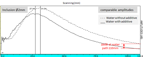
Figure 9 : Experimental results obtained with and without anti rust additive in water, amplitude/distance curves obtained with the Ø2mm inclusion; 5MHz Ø6.35mm flat probe
Continue to Simulation settings
Back to Single element probe