CIVA SHM provides the possibility to simulate Structural Health Monitoring by ultrasonic Guided Waves.
It includes:
- SHM Simulation module
- Mode Computation module
This module is also compatible with the following CIVA features: Parametric Study, Metamodels, POD Study and CIVA Script.
Since Structural Health Monitoring sensors are embedded in the monitored structure, it is even more important than in traditional NDE to design and qualify them carefully before implementation. Simulation tools enable to reduce the number of necessary mock-ups and physical tests to lower costs of design and qualification stages.
With simulation, you will be able to:
- Support the design of the monitoring strategy (i.e. sensors distribution and number depending on the geometry of the structure studied)
- Support performance demonstrations and technical justifications (parametric studies and sensitivity analyses)
- Provide datasets for POD study
- Provide insights and data to better understand / master the technic and how to process SHM signals
Simulation Examples
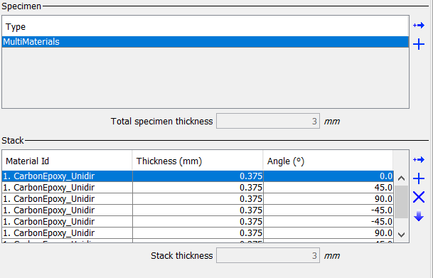
Specimens
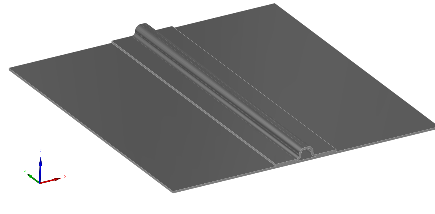
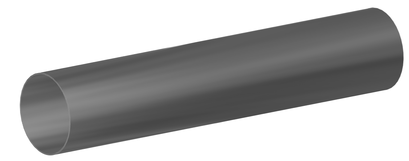
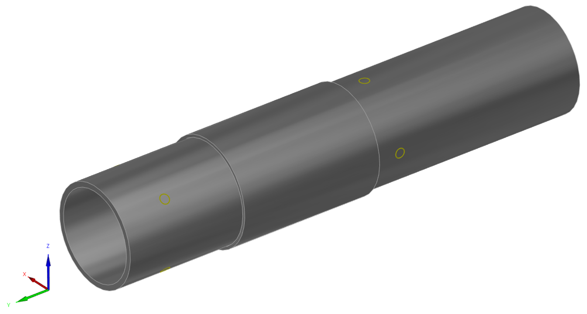
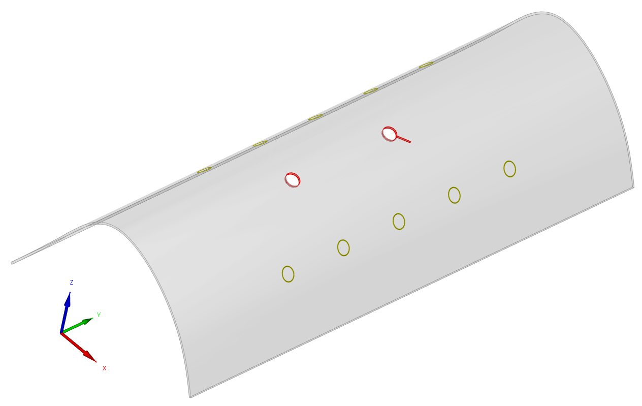
The following parametric geometries are available in CIVA SHM:
- Metallic or composite plate and tubes, possibly multi layers
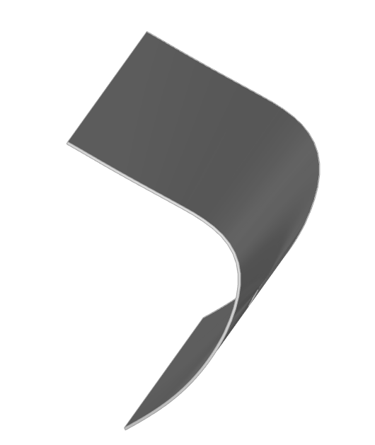
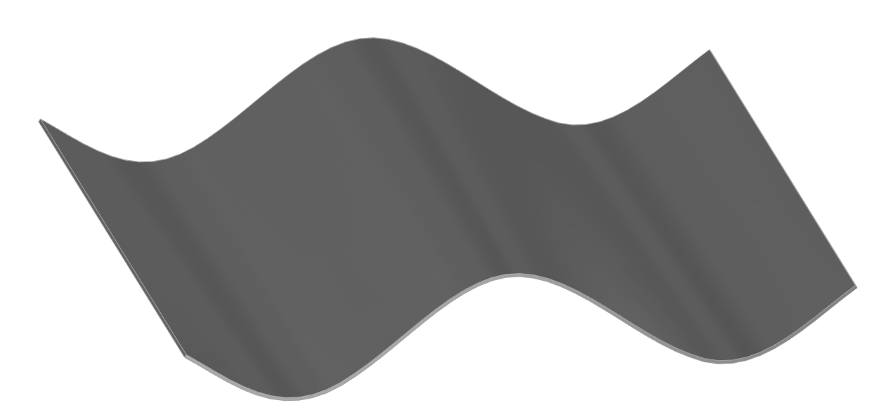
- Curved and deformed panels
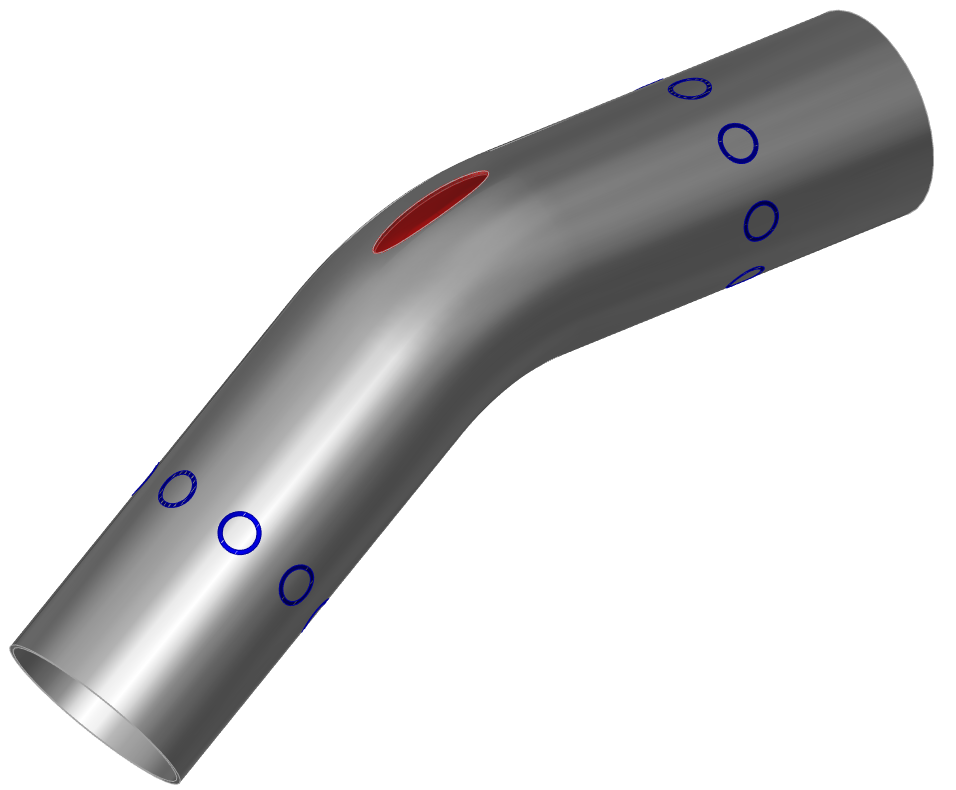
- Elbows
- Stiffener
- Sleeves
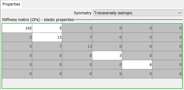
An isotropic material can be defined by providing numeric values for its density and bulk waves velocities. Users can also consider an anisotropic material with an orthotropic or a transversely isotropic crystal symmetry such as in a fiber composite ply, through the definition of the stiffness matrix.
Attenuation can also be accounted for in the component.
Flaws
Several defects can be simulated in a SHM model. The types of available defects are the following:
- Holes, crack connected to a hole, vertical crack, solid inclusions
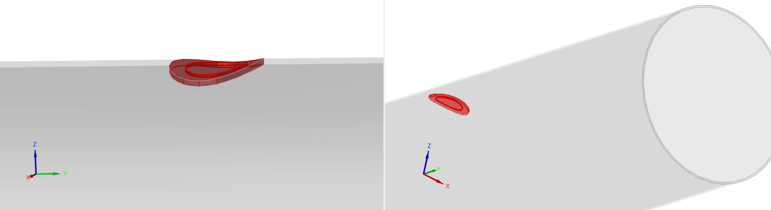
- Delamination (with elliptical or rectangular profiles) for stratified components
- Erosion / Corrosion / Bump profiles (in homogeneous isotropic components only)
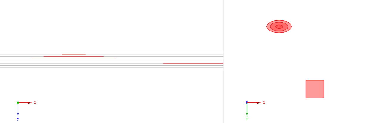
delaminations, erosion-like profiles, holes, crack connected to a hole
Sensors
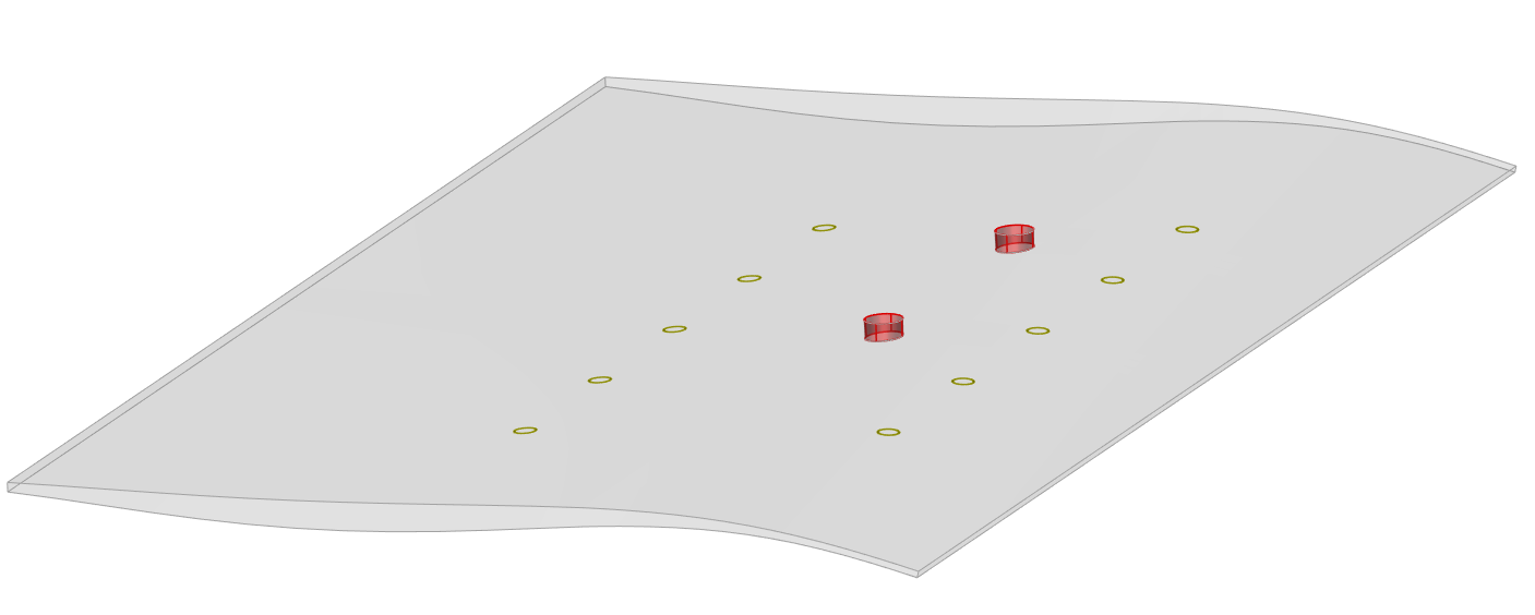
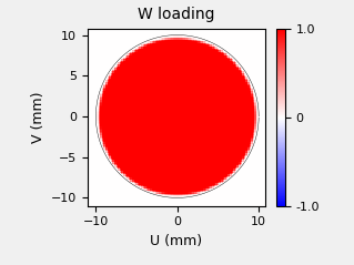
Sensors can have a thin circular shape such as typical piezo electric patches with two possible excitation modes:
- Radial loading: applied on the circumference of the piezoelectric disc (characteristic of low frequency sensors)
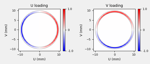
- Normal loading: applied over the whole area of the piezoelectric (characteristic of high frequency sensors)
Custom sensor shapes and loading modes can also be entered by the user, to define an EMAT sensor for instance.
An excitation waveform is associated to the sensor to model the pulse signal. It is based on the definition of the center frequency, the bandwidth or the number of bursts. Custom signals can also be loaded.
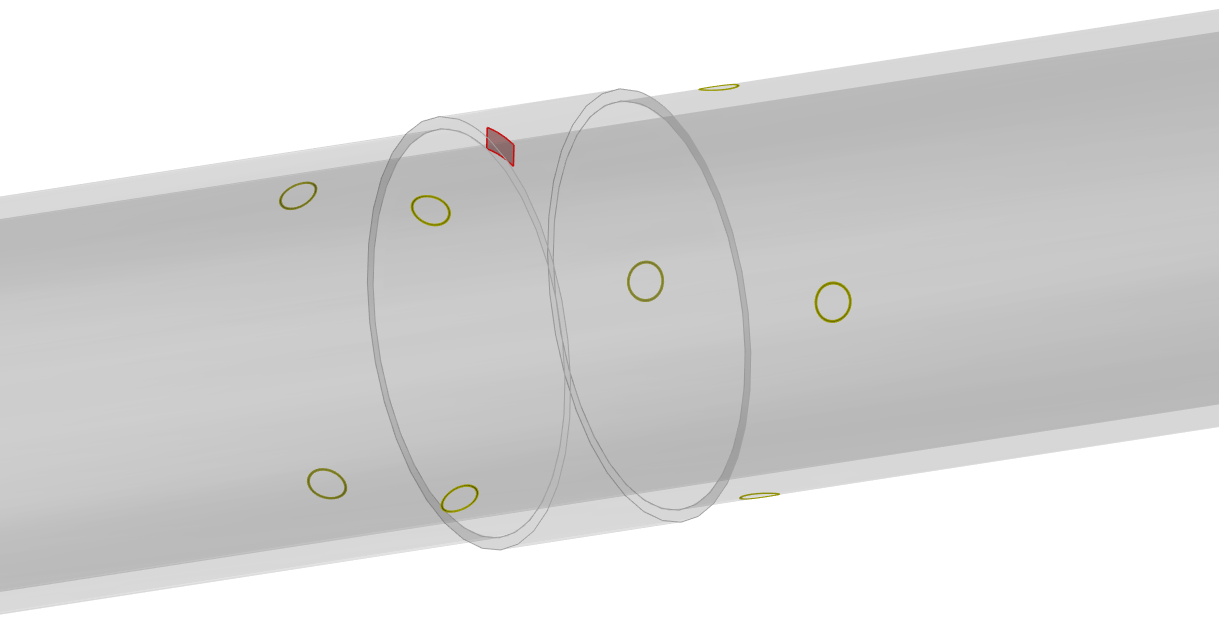
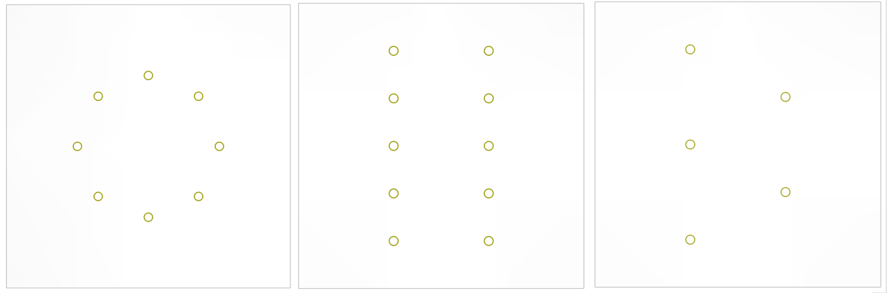
The sensors can be positioned along a circle, a grid or also in a custom way.
They can operate in Round Robin mode (all sensors successively used as transmitters while the others receive) or in custom scan mode.
Results
SHM Simulation
The SHM simulation module uses an optimized FEM technique, the so-called "Spectral Finite Element Model". It relies on high-order Finite Elements built from a macro-element parametric decomposition meshing strategy. CIVA SHM by Guided Waves is fully parallelized and shows very competitive performances, with much faster computation times than traditional Finite Element software (generally higher than a factor 100!), and very low requirement in terms of RAM such that this module can run on very classical computers. Based on parametric geometries, CIVA SHM automates the mesh generation and thus does not require any specific FEM skills from the user. A panel informs the user on the performed automatic mesh, which can be adjusted through one accuracy parameter.
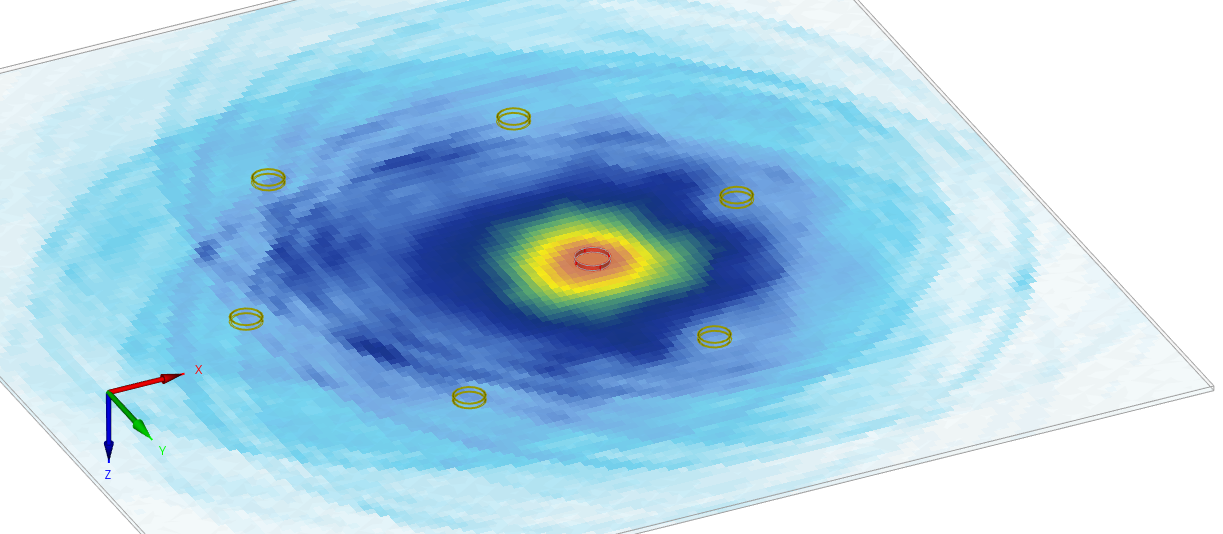
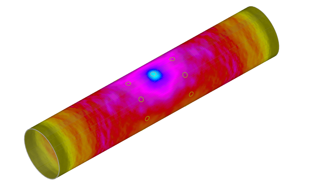
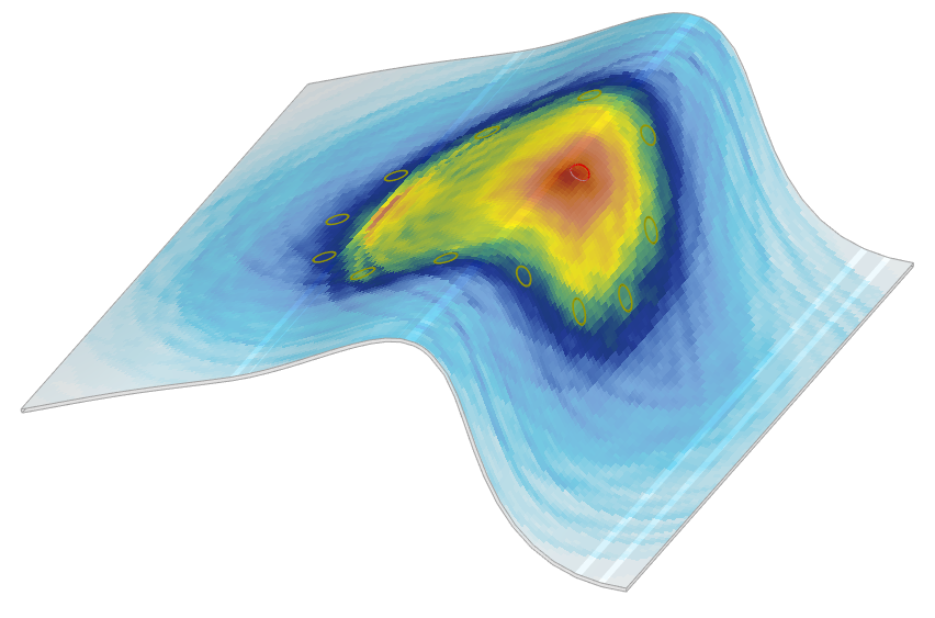
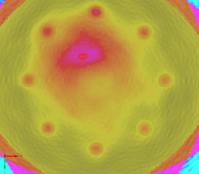
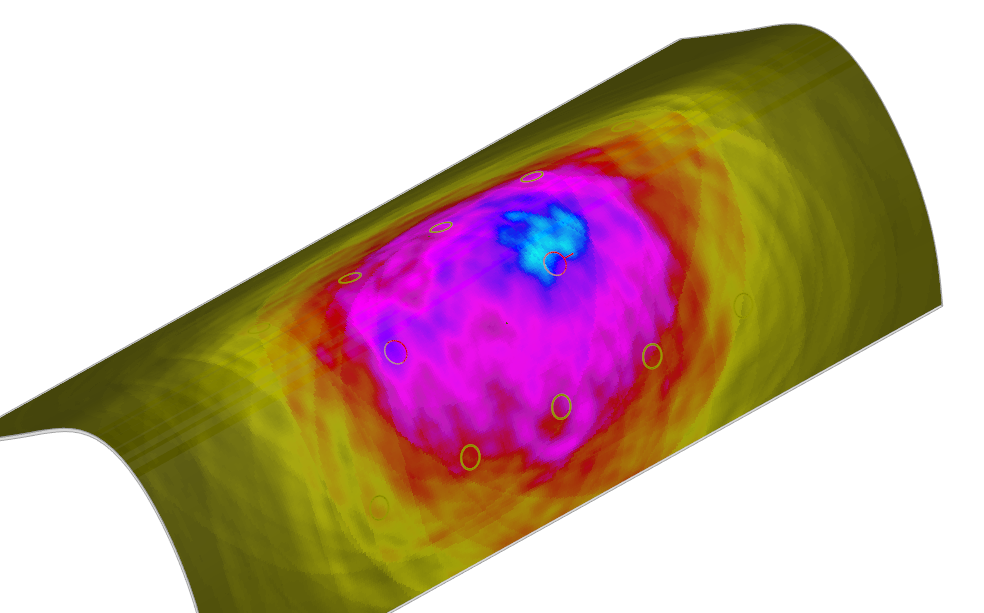
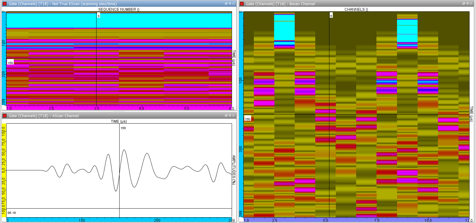
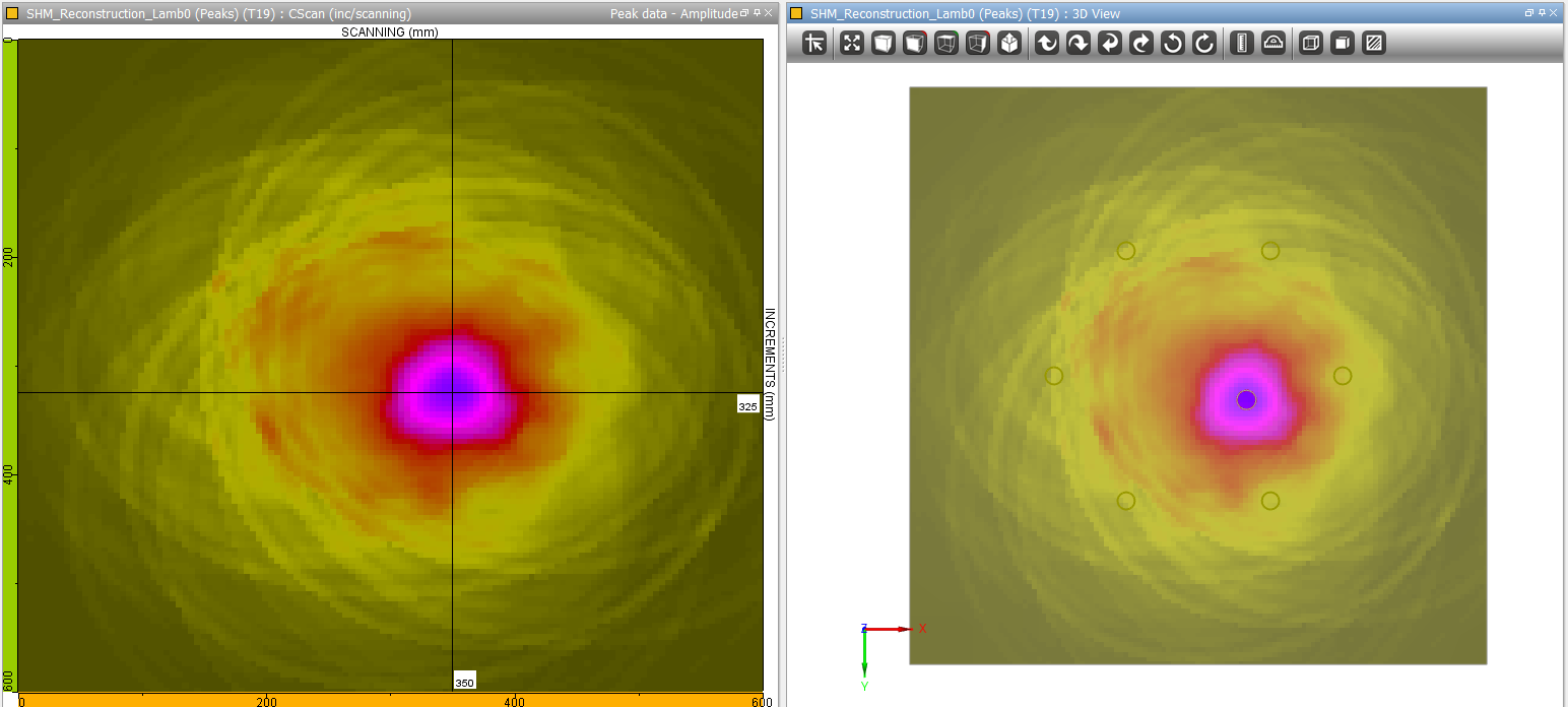
CIVA SHM will compute the signals received on each sensor and for each firing sequence. Symmetric and antisymmetric modes can be separated. From these raw results, a "baseline" subtraction tool is integrated. Some imaging reconstruction algorithms ("Delay and Sum" and "RAPID") are also available to process them and give an image of the defect impact displayed on the specimen 3D view and for different potential reconstruction modes or velocities.
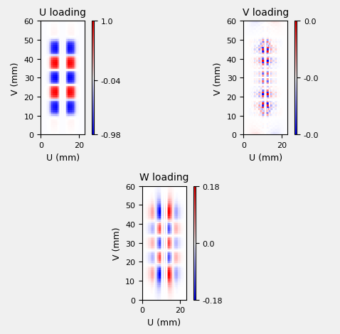
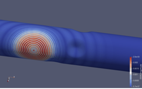
Local fields of displacement and stress can be extracted in *.txt files for various measurement points defined by the user. A *.vtk export enables visualizing snapshots of Guided Wave propagation and mesh information in a VTK viewer such as the freeware Paraview.
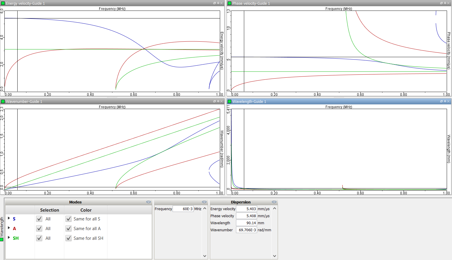
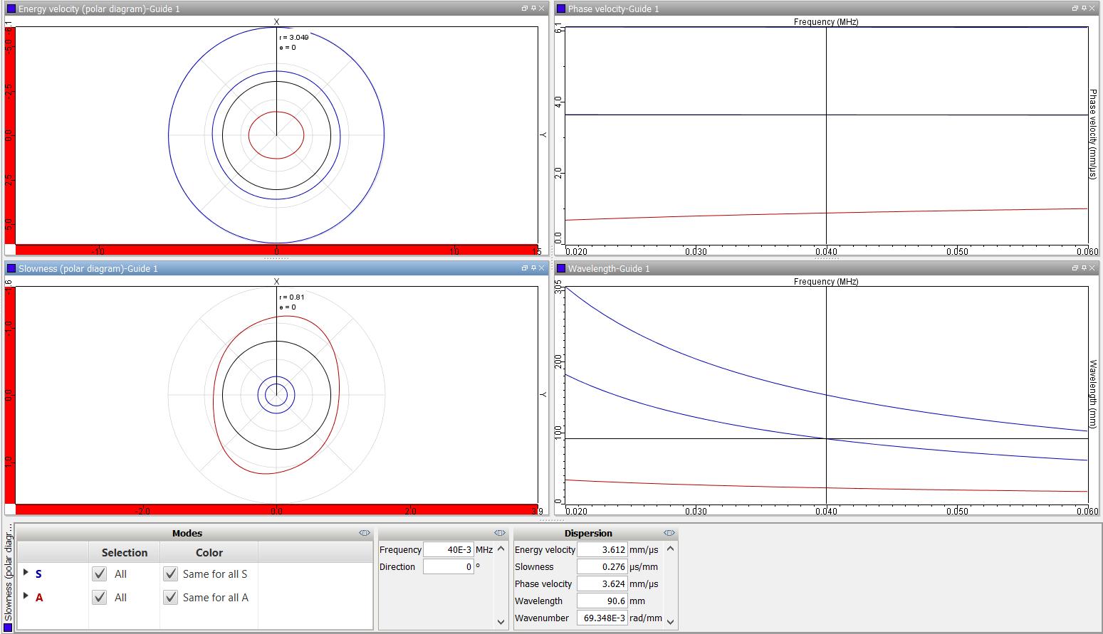
Modes computation
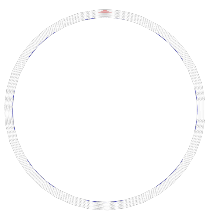
Based on a hybrid so-called "SAFE" method (Semi-Analytical Finite Element), CIVA SHM includes a mode computation tool which simulates the dispersion curves associated to the specimen in a given frequency range. Modal displacements and constraints are also computed. This module is similar to the one available in CIVA GWT.
Planar stratified and cylindrical geometries as well as 2D CAD section waveguide can be defined. Isotropic or anisotropic materials can be considered in this module. In the case of an anisotropic material, in-plane polar representation of dispersion curves is available.