
UT – Corner echoes with SV mode: Simultaneous influence of the notch height and the refraction angle
CONFIGURATION
In the following configuration, the specimen is a ferritic steel mock-up of 30 mm thickness and containing 11 backwall breaking notches of 15 mm length and of different heights: 0.5 mm, 1 mm, 1.5 mm, 2 mm, 3 mm, 4 mm, 5 mm, 7.5 mm, 10 mm, 12.5 mm and 15 mm.
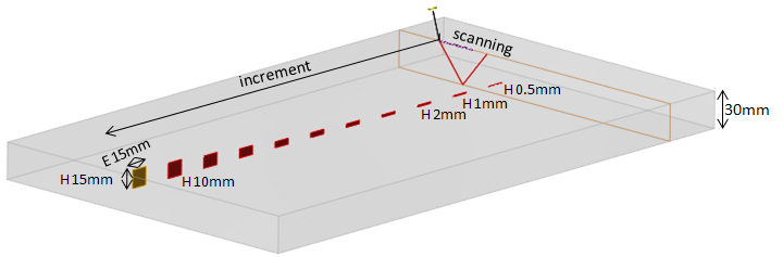
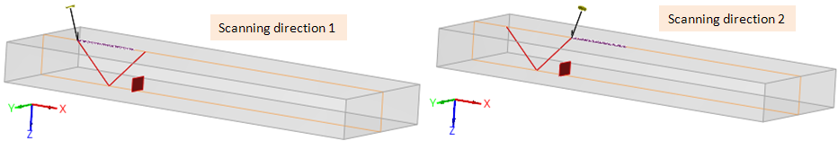
For each probe, measurement are performed along both scanning directions in order to check the homogeneity of the specimen and the measurements reproducibility.
Measurements are performed with two circular immersion probes of Ø6.35 mm diameter. Each one is used to generate, in the specimen, SV40, SV45, SV50, SV55, SV60, SV65 and SV70 waves.
| Frequency | Crystal | Water path | Calibration depth |
| 2.24 MHz | Ø6.35 mm | 25 mm | 20 mm |
| 5 MHz | Ø6.35 mm | 25 mm | 20 mm |
EXPeRIMENTAl results
Inspections are performed with the circular immersion probe of Ø6.35 mm diameter at 5 MHz with a water path of 25 mm. The input signal has a central frequency of 5 MHz, a bandwidth of 66% and a phase of 300°.
The experimental C-scans (below) are displayed for every notch heights and every refraction angles.
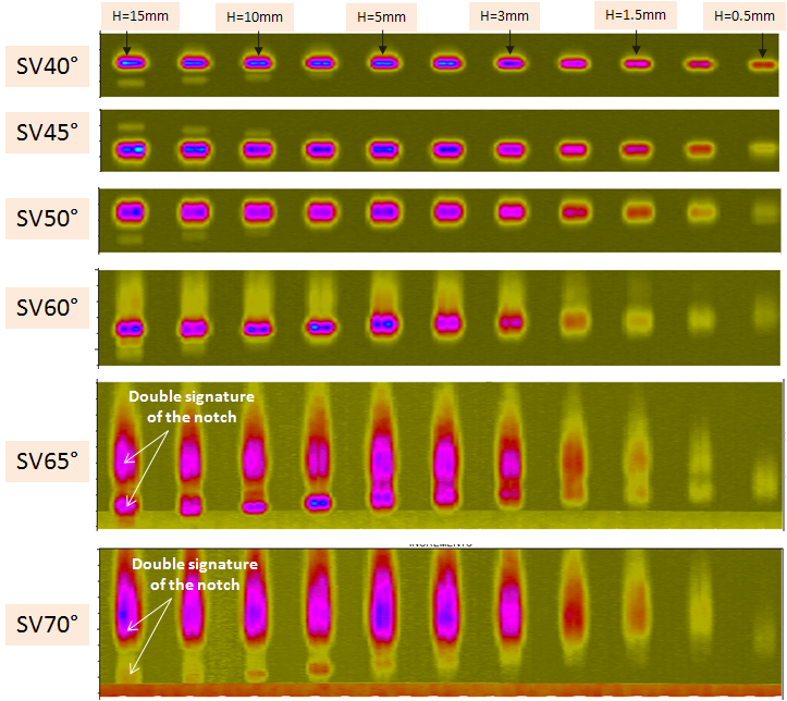
This figure illustrates the inspection of all notches with different refraction angles. It can be seen that for small angles, the notch signature is sharper than for large angles. When the refraction angle increases, the echo becomes larger. For refraction angles between 60° and 70°, the echo splits and shifts. These two phenomena have a common origin, which is explained later.
Comparison between experiments and CIVA simulations
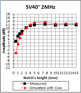
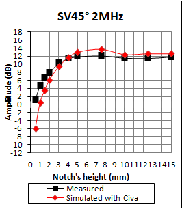
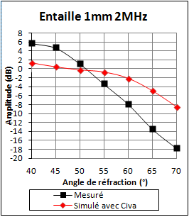
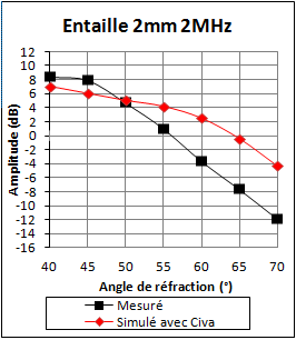
Measurements are performed on backwall breaking notches of 15 mm length. For the following comparisons, the calibration amplitude reference is the SV45 direct echo of a Ø2 mm SDH of 95 mm length located at 20 mm depth. Using this reference for all the refraction angles allows to display the corner echo amplitude versus the refraction angle for all notches heights.
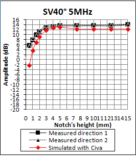
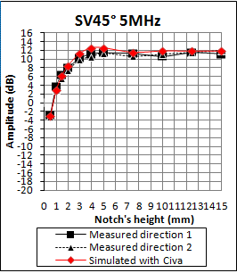
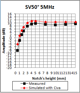
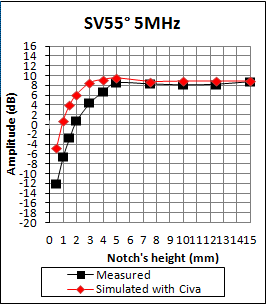
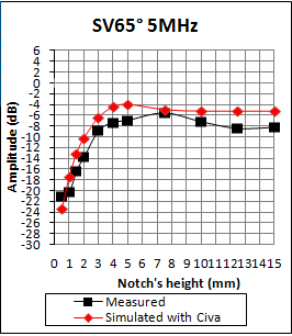
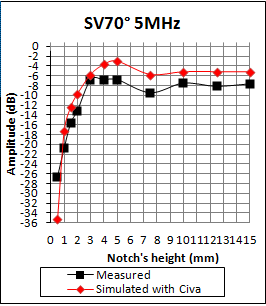
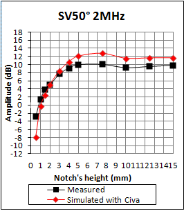
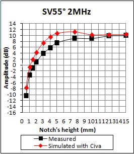
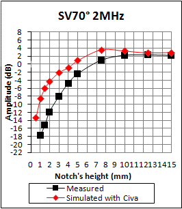
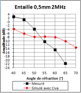
Whatever the refraction angle, a good agreement between experimental and simulated results can be observed for the highest notches (from 4 to 15 mm high). For smaller notches, differences between experiments and simulation can be noticed when the refraction angle is larger than 55°. Furthermore, the smaller is the notch, the larger is the difference (more than 3 dB).
Update : Since CIVA 2020, a Finite Element Model is available in addition of the semi-analytical or analytical models. Contrary to them, the FEM does not suffer from the limitation for small defects. Simulations with FEM for small defects are in good agreement with experiment. Corrections brought by FEM for small defects have been demonstrated here.
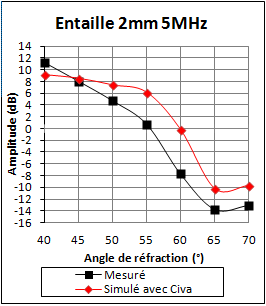
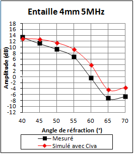
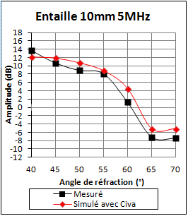
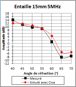
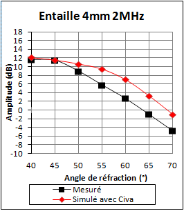
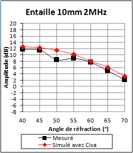
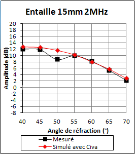
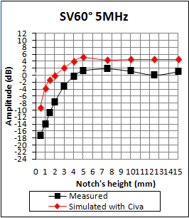
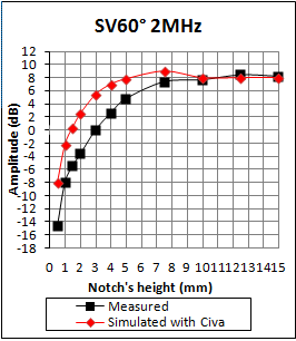
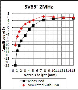
A good agreement between experiment and simulation is observed for the 10 and 15 mm notches. For the 4 mm notch, the largest differences are of the order of 4 dB. The loss of amplitude due to the increase of the refraction angle is well reproduced by CIVA.
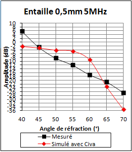
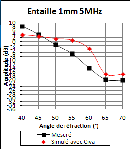
For notches smaller than 4 mm, significant differences can be noticed as the refraction angle moves away from the refraction angles between 50° and 60°. Below these angles, CIVA underestimates the amplitude of the corner echo; above CIVA overestimates the amplitude of the corner echo.
Update : Since CIVA 2020, a Finite Element Model is available in addition of the semi-analytical or analytical models. Contrary to them, the FEM does not suffer from the limitation for small defects. Simulations with FEM for small defects are in good agreement with experiment. Corrections brought by FEM for small defects have been demonstrated here.
Continue to Simultaneous influence of the notch length and the refraction angle
Back to Corner Echoes with SV mode
Back to Corner Echoes