
Multiskip cylindrical: Experimental and simulation setups
Summary
Specimens
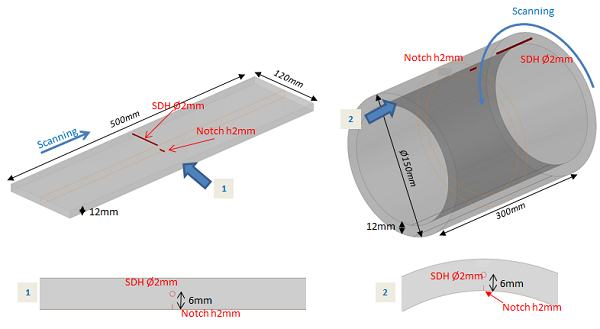
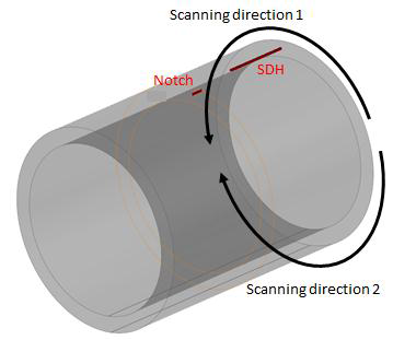
For the study of multiskip echoes, two mock-ups have been constructed: a flat one and a cylindrical specimen of the same thickness. The flat mock-up contains a backwall breaking notch of 2 mm high and 10 mm of extension and a SDH of 2 mm diameter which center is 6 mm from the surface. The cylindrical mock-up contains a backwall breaking notch of the same size and a SDH of 2 mm diameter located 6 mm from the surface. The probe scanning directions are shown on the figure below.
For the calibration of the probe, a third specimen of parallelepiped geometry containing several SDH of 3mm diameter located at different depths has also been manufactured.
These three mock-ups have been extracted from the same steel ingot (structural steel standard: S355 J2) and the flaws in them (notches and SDHs) have been machined so that in each specimen, the fibers are oriented in the same way with respect to the control direction. These requirements are intended to ensure that the material parameters stay the same within the 3 blocks.
Probes
Due to reproducibility problems related to coupling, the experiments were performed in immersion. More information is given in the section “Reproductibility and experimental uncertainties”.
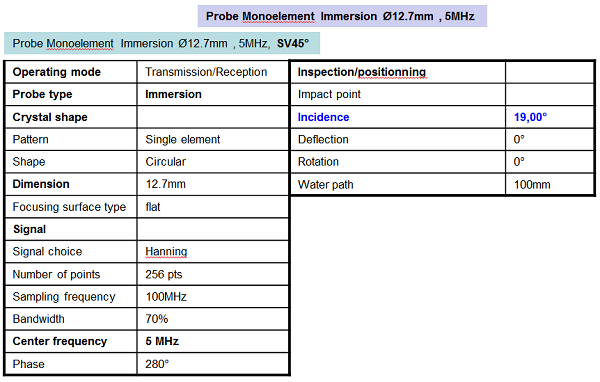
The frequency and the probe aperture were selected so as to have sufficient sound path in order to exploit a maximum of skips. A set of beam simulations resulted in the selection of an immersion probe of Ø12.7 mm diameter and 5 MHz center frequency. The water path was adjusted so that the first corner echo of the notch is located in the far field of the probe.
Angles of incidence
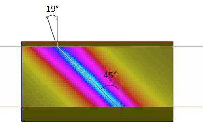
In the planar specimen, the inspection was realized with an incidence angle of 19° allowing to generate T45° waves in the specimen and on the backwall. The figure below shows the radiated beam in the planar mock-up.
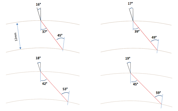
In the cylindrical specimen, the incidence angle must be adjusted to 16° so the T beam generated in the mock-up at 37° intercept the inner surface at 45°. However the T37° beam is close to the T beam refracted at 33° for which head waves generated at the surface of the cylinder contribute to the radiated beam in the cylinder. However, we know that the T refracted beam in the specimen around the critical angle is poorly simulated because the head waves are not taken into account. In these conditions, a less accurate prediction of the notch echoes may be expected. Because we didn’t want to realize an inspection in conditions known to be a source of error in simulation, we chose to increase the incidence angle in order to avoid generation of head waves.
Increasing the incidence angle doesn’t allow to ensure that no head wave will be generated. Furthermore, creeping waves generated at the surface of the notch may appear. For instance, for an incidence angle of 19°, the T45° beam refracted in the specimen intercepts the notch with an angle of 33.5° close to the critical one (33°). These creeping waves may contribute to the echoes reflected by the notch but CIVA doesn’t take them into consideration. This is a second source of error in CIVA when running simulation with an incidence angle of 19°.
Finally, the inspections in the cylinder were performed with incidence angles of 16°, 17°, 18° and 19°. The T waves are then refracted in the specimen with an angle of 37° (i16°), 39° (i17°), 42° (i18°) and 45° (i19°), that is to say increasingly far from the critical angle on the cylinder surface and increasingly close to the critical angle on the surface of the notch. The goal of this slow variation of the incidence angle is to facilitate the results analysis which may be complicated due to the presence of head and creeping waves.
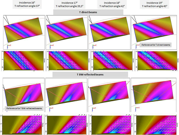
TheT beams, direct and after one skip on the backwall of the specimen, have been calculated with CIVA for incidence angles of 16°, 17°, 18° and 19°. Local directions are displayed where the amplitude of the beam is larger that -6dB compared to the maximal amplitude of the zone. It can be seen on the figure below that the maximum amplitude of the T direct beam is located near the cylinder backwall only for the 16° incidence angle. For incidence larger than 16°, the maximum of the beam is located above the backwall. The T beam after one skip is more divergent as the incidence angle increases.
Probe input data in CIVA
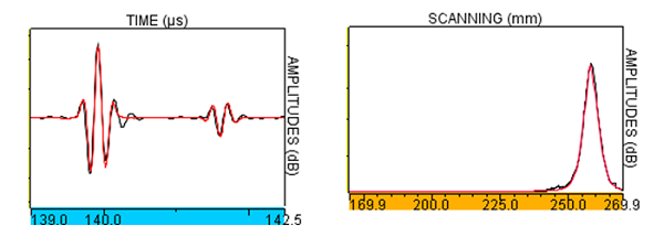
The entry signal of the probe has been chosen so the experimental and simulated T direct echoes of a SDHØ2mm located at 6mm depth in a planar specimen of 12mm thickness are in good agreement.
Simulation parameters
Simulations were performed with CIVA2015 (CIVA 11.1)
The input parameters of CIVA are reported below:
| L wave velocity | T wave velocity | Density | Attenuation |
| 5950 m/s | 3290 m/s | 7.8 g.cm-3 | Attenuation pour T wave (cf. chapter « Attenuation ») |
The L and T waves velocities were obtained with experimental measurement of several and successive times of flight of backwall echoes obtained in the calibration block of 110mm thickness. A L0° probe of 5 MHz has been used for the measurement of the L wave velocity while a T0° probe was used for T wave velocity measurement.
The simulations accuracy is 3 for both beam and defect calculation.
Echoes simulated with CIVA
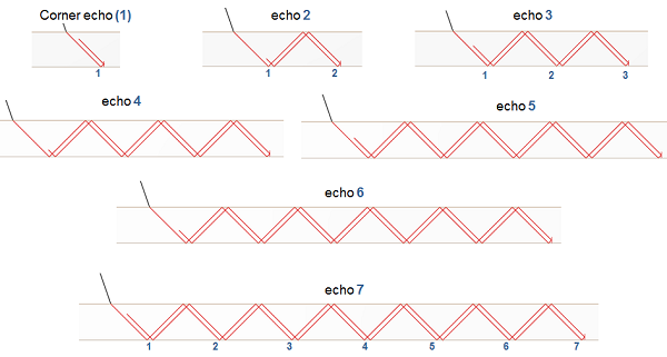
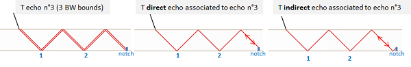
During the multiskip inspection in T45° mode of a backwall breaking notch, several echoes of important amplitudes corresponding to different paths “probe-notch-probe” appear. In the following, they will be numbered from 1 to 7.
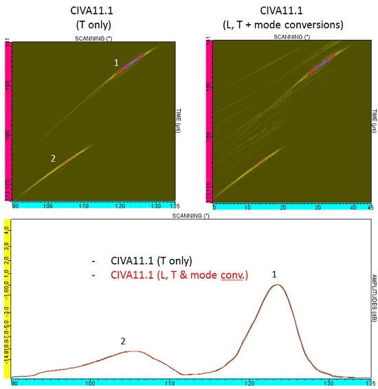
Due to computation times and limitation of modes possible to simulate in the same time in CIVA, the number of modes has been limited. The simulation presented have been performed with T waves only. It has been checked that not taking into account mode conversion doesn’t change the amplitude of multiskip echoes of the notch (see example below for incidence angle of 16°).
Furthermore, with the objective of reducing the number of calculated modes, all the possible T echoes have not been simulated. Indeed, the automatic list of modes proposed by CIVA is very long when the number of skips increases (105 T modes when considering 7 skips on the backwall). A lot of them do not contribute to the echoes of interest so it is not necessary to simulate them all. Thus, a list of modes has been defined manually in order to simulate only some of them. This list contains:
- The multiskip echoes described above
- Direct and indirect echoes associated to each multiskip echo
Thus, for defect response simulation after 7 skips, there are 21 T modes.
Reproducibility and experimental uncertainties
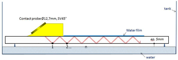
A preliminary study was conducted to define the multiskip configuration the most appropriate for validation and its implementation. The experiment was to evaluate the response of multiskip echoes in a flat part for the following three coupling conditions (figure below):
- Air above the specimen and air under the specimen
- Water film on the entire surface of the specimen and air and below the mock-up surface
- Full immersion of the specimen in water.
Reproducibility tests were performed in the 3 cases.
The results of the tests performed at two different frequencies (2.25MHz and 5MHz) are shown below. The series of acquisitions have shown that only the results in the case of full immersion are reproducible.
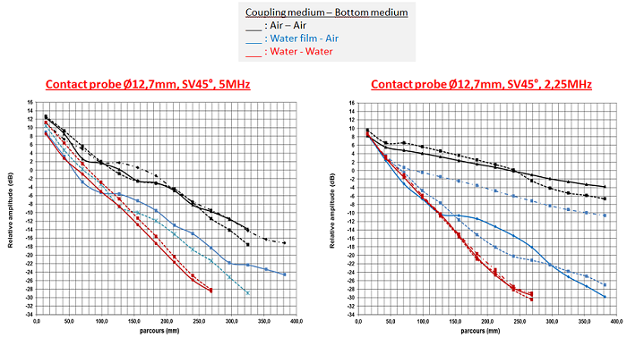
The immersion implementation was therefore chosen for the study of multiskip echoes.
In order to evaluate the experimental uncertainty due to mechanical parameters, machined defects and inhomogeneity of the material, reproducibility tests have been performed. For example, the notch located in the cylinder has been inspected along 2 scanning directions (see figure below).
The results obtained after these 2 inspections and the superimposition of the 2 echodynamic curves are reported on the figure below. The maximal difference between both measurements is lower than 1dB.
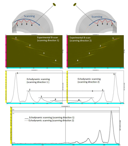
The confidence interval for experimental results has been estimated to +/-2dB (1dB due to the uncertainty of the measurement for the reference reflector and 1dB due to the uncertainty of the measurement on the defect of interest).
Continue to Measurement of the attenuation
Back to Multiskip echoes on cylindrical specimen