In the flat specimen, a good agreement was obtained between the measurement and the predictions of CIVA for the notch multiple echoes.
In the cylindrical mock-up, significant differences for all the multiskip echoes were observed regardless of the incidence angle (16°, 17°, 18° and 19°). These differences related to the amplitudes of the echoes, to the shapes of their echodynamic curves and Ascans were analyzed in two stages:
- Study of the differences obtained on the corner echoes notch. The ATHENA2D model was used for interpretation of these echoes.
- Study of the differences obtained for the following multiskips echoes. It is not possible with ATHENA2D to calculate the multiple echoes of the notch beyond the first corner echo because the paths associated with these echoes include a skip on the surface of the specimen which is not allowed in the finite element calculation zone of ATHENA2D. Without knowing with certainty the attenuation parameter in the cylinder, the role of attenuation was first studied. The effect of the attenuation increases with the number of skips. Finally, we discussed the possibility of extrapolating the sources of errors identified for the corner echoes to the multiskip echoes.
Corner echo
- Of the presence of head waves on the surface of the cylinder. Indeed, these waves appear for angles of incidence close to 16°. They contribute to the T refracted beam in the specimen. CIVA does not take them into account and this may result in differences between the real emitted beam in the cylinder and the one predicted by CIVA.
- Of the presence of creeping waves on the surface of the notch. Indeed, these waves can appear for incidence angles close to 19°. They can contribute to the corner echo reflected by the notch. CIVA does not take the creeping waves into account and this can lead to discrepancies between the experimental corner echo and the one simulated with CIVA.
- Of the presence of creeping waves on the cylinder backwall. During inspections with incidence angles between 16° and 19°, the incidence angles at the backwall of the specimen vary from 45° to 60°. This is far from the critical angle at the backwall of the specimen and generation of creeping waves is not expected after the skip of the beam on the backwall of the part.
- Of the beam approximation in CIVA when computing its interaction with the notch. The approximation consists in describing in a simplified way the overall beam of the probe by a temporal shape, a direction of incidence, an amplitude, a phase and a time of flight. This approximation is valid if the notch is located in the far field of the transducer.
Effect of the creeping waves ate the surface of the notch
In order to take into account the creeping waves generated at the surface of the notch, the ATHENA2D model was used. This is a "2D" model which results were compared with those of CIVA2D. The simulations with ATHENA2D and CIVA2D were run without taking into account attenuation.
Shape of the echodynamic curves
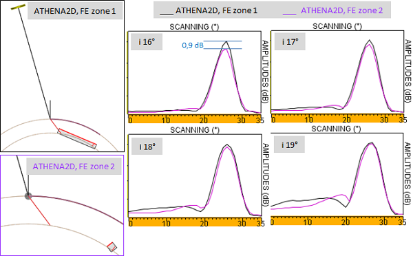
The CIVA2D and ATHENA2D corner echo echodynamic curves, calculated for the 4 incidence agles were superimposed on the figure below (the box used for finite element calculations is shown on the left of the figure for incidence angle of 16°, the boxes used for other inspections (17°, 18° and 19°) are similar).
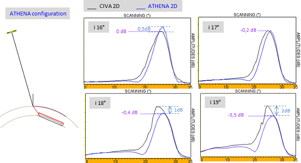
These results show that:
- The more the incidence angle increases (from 16° to 19°), the more the CIVA2D and ATHENA2D shape of echodynamic curves differ. This is consistent with the fact that the creeping waves generated at the surface of the notch are more important, and therefore change even more the shape of the echodynamic curves of the corner echo. Indeed, the angle of incidence of the T waves on the surface of the notch is close to the critical angle.
- For all incidence angles, ATHENA2D echodynamic curves are narrower than those of CIVA2D. Moreover, for the incidences of 18° and 19°, the ATHENA2D and CIVA2D amplitudes differ (by 1 and 2 dB difference).
- The amplitudes of corner echoes obtained with incidence angle of 16°, 17° and 18° are close, but the one of the corner echo at incidence of 19° is 3.5dB lower.
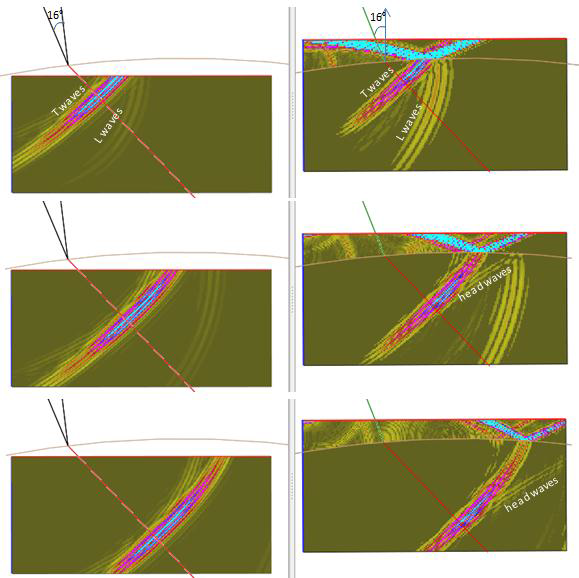
The effect of the presence of creeping waves is illustrated on the figure below where are illustrated the waves propagation in the specimen and their interaction with the notch in the following configurations:
- Flat specimen inspected with 19° incidence angle (T45° on the notch)
- Cylindrical specimen inspected with incidence angles of:
- 16° (T44° on the notch)
- 17° (T41° on the notch)
- 18° (T37° on the notch)
- 19° (T33.5° on the notch)
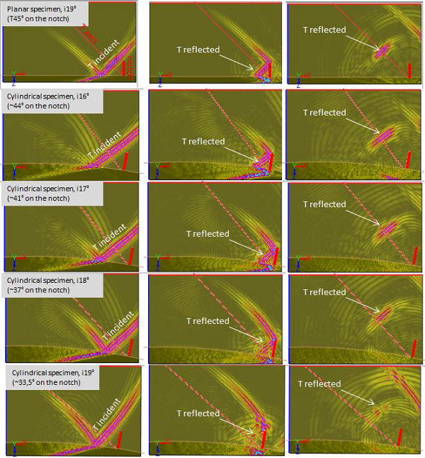
In the flat specimen, the T wave backscattered by the notch follows the incident T axis.
In the cylindrical specimen, the T-wave backscattered by the notch follows well the incident T axis of the beam when the incidence is 16°. Then, the larger the incidence angle is, the more the T wave reflected by the notch is deflected at the right of this axis. At the incidence of 19°, the reflected T wavefront is deflected and presents a "hole" that is attributed to the presence of creeping waves on the notch. This disturbed wavefront is in good agreement with the decrease in amplitude of the corner echo (-3.5dB).
Position of the probe at the maximum of the corner echo amplitude
Due to the contribution of creeping waves generated at the surface of the notch on the corner echo, the position of the probe at which the maximum amplitude is obtained does not correspond to the position at which the axis of the T-wave intercepts the base of the notch.
In the case of 16° incidence angle, there is no creeping waves on the flaw and the maximum amplitude of the corner echo is obtained when the axis of the T-wave intercepts the basis of the notch (Figure below top left, ATHENA2D result).
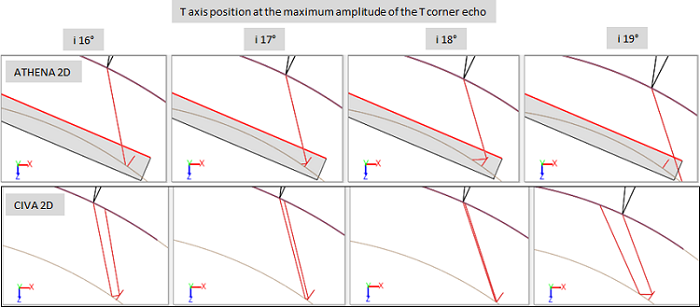
The more the creeping waves contribution is important (when the incident angle tends to 19°), the more the corner echo maximum amplitude appears when the beam axis intercepts the backwall beyond the notch (Figure above the top right, result ATHENA2D).
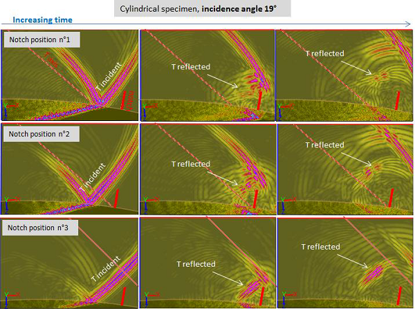
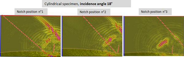
The visualization of the beam reflected by the notch in function of its position relatively to the axis of incidence of the T-wave allows to illustrate this offset.
- At the incidence of 19°, the corner echo maximum of amplitude is obtained when the notch is located before the T axis (figure below, top right). This corresponds to the position n°3 on the figure below. At this position, the angles of incidence on the notch of the beam which intercepts it are not critical. The reflected T field is not disturbed by creeping waves. On the contrary, when the notch is on or in front of the T axis (position n°2 and n°1 on the figure below) the reflected front is disturbed and the amplitude of the corner echo reflected by the nocth at these positions is less important.
- At incidence angle of 16°: the maximum amplitude of the corner echo is obtained when the T axis intercepts the bottom edge of the notch (see figure below).
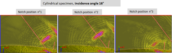
- At the incidence angle of 18°, creeping waves are always present but only when the notch is located after the axis T. The T reflected wavefront is disturbed at this position of the notch whereas it is not is when the T axis intercepts the base of the notch (see figure below).
These results obtained with CIVA2D and ATHENA2D highlighted the need to take into account the creeping waves generated on the surface of the notch when the incidence angle is close to 19°.
Extrapolation to "3D" configurations
The need to take into account the creeping waves on the notch has been demonstrated using "2D" calculations. It remains valid for 3D configurations and explains partially the differences between the measure and the CIVA predictions (3D calculations) at incidence angles of 19°. We saw that ATHENA2D predicts narrower echodynamic curves than CIVA2D. This suggests that taking into account creeping waves in 3D would reduce the width of the echodynamic curves and thus make them closer to the experimental ones.
Effect of the head waves ate the surface of the cylinder
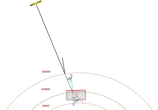
Not taking into account the creeping waves on the notch cannot explain the discrepancies between measurement and simulation for incidence angles of 16° and 17° for which the associated incidence angles on the notch are far from the critical angle. The differences may be due to head wave generated on the surface of the cylinder because the incidence of 16° is close to the critical incidence angle for L waves (14.5°). Then, this would be the T beam refracted in the specimen that would be poorly predicted by CIVA which do not take into account the head wave.
"2D" calculation with ATHENA 2D
To highlight the head wave generated at the surface of the cylinder with ATHENA2D a "bilayer" configuration was simulated. It consists in creating a cylindrical specimen where the material of the upper layer is water, the second layer (of identical thickness to the cylinder) is made of steel. This allows to take into account the surface of the specimen in the ATHENA2D calculation box and to simulate head wave generated in the water/steel interface.
The beam calculated in the bilayer configuration is compared to the T refracted beam in the monolayer cylinder. The figure below shows the results obtained and the superposition of the echodynamic curves extracted at the depth indicated on the figure.
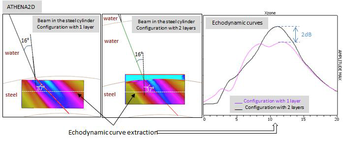
This superimposition shows a difference between the two echodynamic curves. The beam obtained in the bilayer cylinder is narrower. This difference is attributed to the consideration (bilayer) or non-consideration (monolayer) of the head wave on the T radiated beam under the surface of the cylinder. The beam calculated by CIVA2D is close to the one obtained with ATHENA2D in the monolayer configuration (figure below). The calculations were performed without attenuation.
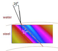
The figure below illustrates the presence of the head wave.
Extrapolation to "3D" configurations
The need to take into account the head waves generated at the surface of the cylinder was highlighted by "2D" calculations. It remains valid for 3D configurations and partly explains the discrepancies between the experiment and the predictions of CIVA (3D calculations) for incidence angles close to 16°.
The calculations performed with CIVA in "3D" showed that for the notch, the experimental echodynamic curve of the T corner echo is narrower than the one simulated with CIVA for angles of incidence of 16° and 17°. However, the previous result obtained in "2D", showed that the echodynamic curve of the T beam in the cylinder is narrower when head waves are taken into account. Therefore it can be expected that, in "3D", taking into account head waves in CIVA when calculating the notch corner echoes leads to narrower echodynamic curves, thus closer to the measurement.
Effect of creeping waves at the backwall of the cylinder
The ATHENA2D calculations of corner echoes at incidence angles of 16°, 17°, 18° and 19° with a finite element box encompassing a large portion of the backwall in front of the notch were re-launched with a box much smaller around the defect (box shown in Figure below, at left). The contribution of creeping wave generated at the backwall of the cylinder on corner echoes is then ignored. However, the results obtained with this little box are very similar to those obtained with the large box (the echodynamic curves obtained with the 2 boxes are superimposed on the figure below). This confirms that there are no creeping waves generated at the bottom of the cylinder which contribute to the corner echoes. This is not surprising because the angles of incidence at the bottom of the specimen are far from the critical angle for the 4 studied incidence angles.
Effect of the beam approximation on the defect response
To overcome the beam approximation during defect response simulation, the single-element probe has been replaced by a sectorial annular phased array transducer composed of 200 elements. The corner echoes of the notch were calculated with this probe using the KIRCHHOFF + GTD model and activating the runtime variable "MULTI-VOIES". This allows a more precise description of the beam used for the calculation of the interaction with the notch because the defect response is performed by summing the elementary echoes calculated for each pair of emitter-receiver. Thus, the defect response calculation does not use the global beam of the probe but as many elementary beams as there are couples of elements on the transmitting surface.
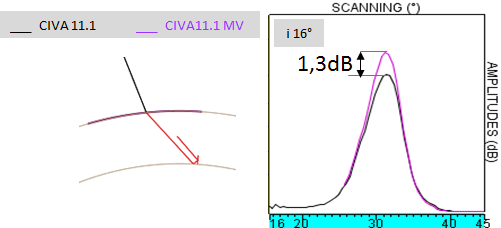
For reasons of very high computation time with the runtime variable "MULTI-VOIES", simulations were performed only for the notch corner echo at the incidence angle of 16°. The attenuation parameters used are the ones of the flat specimen (coefficient of 0.045 dB/mm). The results obtained with the phased array probe and the runtime variable "MULTI-VOIES" are called CIVA11.1_MV.
Compared to the results obtained without the runtime variable, T amplitudes of corner echoes are 1.5dB stronger with CIVA11.1_MV while shapes of echodynamic curves are very similar (see figure below). Furthermore, the amplitude calculated with CIVA11.1_MV of the direct echo of a SDH located in the flat specimen at the incidence of 19° (calibration echo) is also 2dB stronger. Thus, the relative amplitude of the corner echo with respect to the reference is almost the same with CIVA11.1_MV and CIVA.
To conclude: the beam approximation for calculation of the interaction with the flaw does not explain the differences observed between CIVA and experiments.
Multiskip echoes after the corner echo
For multiskip echoes after the first corner echo, the observed differences depend on the value of the attenuation coefficient. CIVA underestimates the amplitudes and the difference with the measure increases with the number of skips. Thus, it is difficult to analyze the differences obtained since CIVA predictions depend very strongly on the value of the attenuation coefficient. However, this value has not been determined with certainty for the cylindrical part. Then, the differences may be due to wrong attenuation parameters, but they can also be due to:
- Like corner echoes, to errors associated to the non-consideration of creeping waves. These errors may be cumulative with the number of skips.
- To other phenomenon unobserved for corner echoes and unaccurately considered by CIVA. They may appear when the number of skips increases.
AttEnuation
CIVA predictions for multiskip echoes of the notch in the cylinder are not in good agreement with the measure when simulations are performed with the attenuation coefficient determined in the flat specimen (0.045 dB/mm). Assuming that the differences are due to poor estimation of this coefficient, we simulated inspections of the notch for incidence angles of 16° and 19° by varying the attenuation coefficients in an attempt to find one that would predict amplitudes in accordance with the measurement.
The comparison of the simulated and experimental amplitudes with different values of the attenuation parameter (0.005 dB/mm, 0.015 dB/mm and 0.025 dB/mm) are presented below.
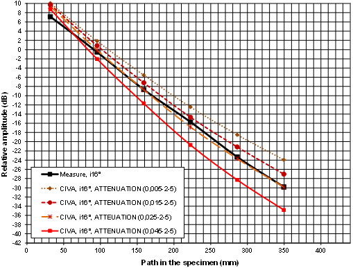
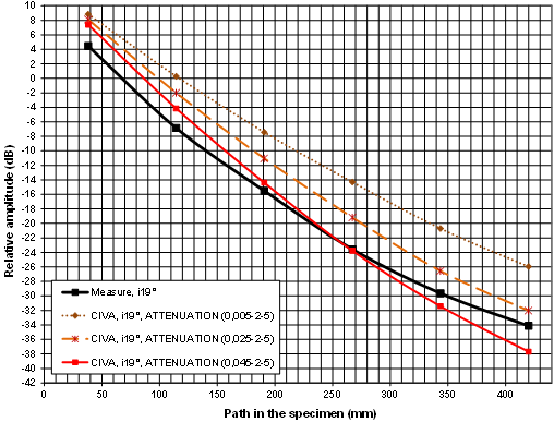
These results show that the coefficient of 0.025 dB/mm seems to be the most consistent for modelling of the amplitude. With this coefficient:
- At incidence angle of 16°, the good agreement between simulated and experimental amplitudes may be due to the fact that there is less effect related head waves on the notch located at the bottom. Nevertheless, the spatial distribution of the field is probably poorly modeled at the bottom which impacts the echodynamic curves.
- At incidence angle of 19°, the slope is fairly well predicted. There is a difference in amplitude which varies slightly with the number of skips. The presence of head waves propagating on the defect may explain these differences. However, creeping waves are generated only once (during the interaction between the beam and the notch), and therefore the error is not cumulative when the number of skips increases.
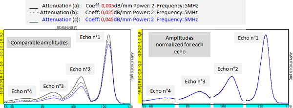
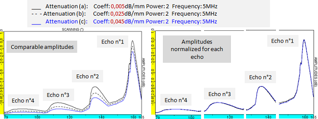
It is important to note that the shape of echodynamic curves does not dependent on the attenuation coefficient. This is illustrated by the superimposition of the simulated echodynamic curves with 3 different coefficients for the first 4 multiskip echoes. The 3 echodynamic curves of each echo perfectly overlap when they are normalized in amplitude (figures below, on the right for incidence angle of 16 ° (top) and for the 19° incidence angle (bottom)). Thus, echodynamic curves that are poorly predicted by CIVA with the attenuation coefficient of 0.045 dB/mm won’t be better simulated if the simulations are performed with another attenuation coefficient. The value of the attenuation coefficient has an effect on the evolution of the echoes amplitudes with the number of skips (figures below, on the left).
Finally, the simulations performed with different attenuation coefficients show that the attenuation coefficient of 0.025 dB/mm allows to correctly predict the evolution of the amplitudes of the multiple echoes of the notch when the number of skips increases (for incidences included between 16° and 19°). It may be assumed that the difference (constant with the number of skips) between the simulated and experimental amplitudes at 19° and the differences on the shapes of the echodynamic curves for all incidence angles are due to the presence of head waves and creeping waves generated on the surface or on the notch.
EffeCt of the creeping waves at the surface of the notch
We have seen that the creeping waves generated on the surface of the notch are more important and alter the shape of the echodynamic curve of the corner echo when the incidence angle goes from 16° to 19° because it is closer to the critical angle.
This is valid for all multiskip echoes: the creeping waves can be generated on the notch for each of the skips. However, they appear only once, during the interaction of T waves with the notch. Furthermore, their effects are not cumulative when the number of skips increases.
Effet of head waves during successive skips of T waves on the surface and on the backwall of the cylinder
Considering an incident ray at an angle i with respect to the surface of the cylinder, during the successive skips of this ray on the bottom (or the surface) of the specimen, the angle of this ray with the normal to the bottom (or the surface) is the same for all skips.
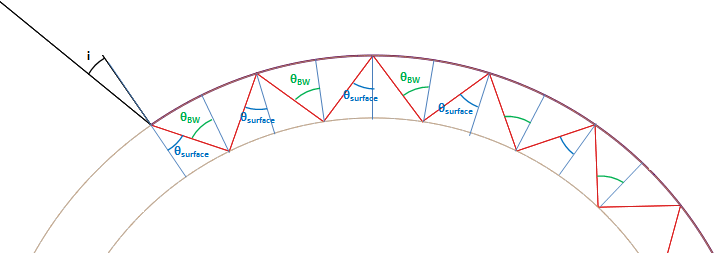
These angles being kept during the successive skips, the effects of creeping waves observed for the echo corner can be extrapolated to multiskip echoes. Therefore when generating these multiskip echoes, it can be expected:
- Effects of head wave during the successive skips of T waves on the surface of the cylinder when the incidence angle is close to 16°. As CIVA does not take them into account, it is possible that errors related to an inaccurate simulated beam after each skip accumulate when the number of skips increases. However, it is not possible to confirm this by highlighting these waves.
- Effect of creeping waves at the surface of the notch for angle of incidence near 19°. These creeping waves are generated only once during the interaction beam/notch. As CIVA does not take them into account, this causes an error in the prediction of each multiskip echo. This error is not cumulative when the number of skips increases. Again, it is not possible to confirm this by highlighting these waves.
- No effect of the creeping waves on the backwall of the cylinder
These extrapolations take into account the angles associated with the central ray of the probe during the successive skips and may be nuanced by the fact:
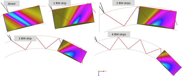
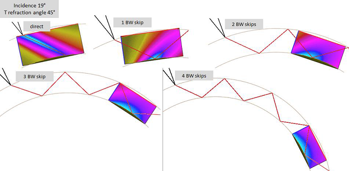
- The T beam does not exactly follow the central ray of the probe during the successive skips of the beam on the bottom and on the surface of the cylinder as shown on the figures below. At the incidence of 19°, for the first skip, the beam is along the axis. On the contrary, at the incidence of 16°, the beam deviates from the axis after the refraction on the surface of the cylinder. This difference is due to the strong decrease of the transmission coefficient value.
- The beam is quickly divergent when the number of skips increases.
Thus, during the successive skips, the angles of incidence on the backwall and the surface of the specimen do not correspond to the ones of the central beam. Many angles are taken into account and it is difficult to predict where the creeping waves can be generated. The fields do not contradict a priori the assumptions on head waves at the surface but the divergence complicates the situation after N skips.
Continue to Side Drilled Holes: interpretation of the comparison results