
Corner echoes with P mode: Conclusion and discussion on discrepancies
Summary
CONCLUSION
For the notches, probes and specimens used for this validation study of the P45 and P60 inspections of vertical backwall breaking notches, a very good experience/simulation agreement is obtained for the P corner echoes amplitudes (difference less than 2 dB) except for notches small relatively to the wavelength. The causes of this difference is the limitation of the Kirchhoff model when applied to small notches, the low probe frequency and the mixture of the notch diffraction echo with the corner echo.
In the case of mixed and SV corner echoes, some discrepancies sometimes occur between the experimental results and the simulation predictions. These discrepancies occur mainly for the more divergent probes and mainly because the SV beam refracted in the specimen during P45 and P60 inspections is not well modeled with CIVA. Due to the strong variation of the P->SV transmission coefficient near the critical angle, the CIVA beam computation mode predicts a beam splitting in two for both the transmitted and the backwall reflected beams in SV mode. This split is not realistic; however its effect doesn’t always alter the corner echo amplitude.
Further studies will be conducted on this topic.
Differences discussion
Several assumptions can explain differences between experiments and CIVA predictions:
- The “small defect” limitation of the Kirchhoff interaction model
- Critical contributions, or creeping waves, in particular for divergent beams
- The SV beam splitting
The “small defect” limitation of the Kirchhoff interaction model
In some cases, as for the immersion probes functioning at 2 MHz, discrepancies can be noticed, in particular for small defects. Some of these differences can be explained by the interaction model limits.
Indeed, the Kirchhoff beam-defect interaction model was developed for specular reflections at high frequency. This implies that the defects radius (here, the half-height of the notch) should be larger than the wavelength and that the associated notch edges diffraction contributions are not simulated. The validity of the model is ensured according to a criteria based on the product of the wavenumber (k = 2*π/λ) with the defect radius (a): k.a>>1.
At 2 MHz, with a phase velocity in steel of 5900 m/s for P waves, the wavenumber k is 2.1 and the notch height must be larger than 0.9 mm. This explains why simulation is less accurate for notches of 0.5 mm or 1 mm height.
Furthermore, it has been shown that the probe central frequency is not the only parameter that influences the Kirchhoff limitation, the bandwidth also has an influence. This last one is not studied in this document because all the probes that have been used have a bandwidth of almost 60%.
Critical contributions, or creeping waves, in particular for divergent beams
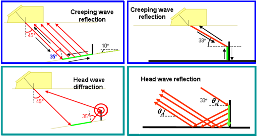
These phenomena are due to the presence of contributions in the beam arriving on the specimen backwall and/or the notch surface at incidences greater than the critical one which can lead to the generation of surface waves (note that the refraction angle for SV waves corresponding to the critical incidence angle in steel is 33° on the backwall and 57° on a vertical notch). Contributions due to the creeping waves and the head waves can explain differences observed on echodynamic curves since they provide additional contributions to the corner echo.
The image below illustrates the contribution of the creeping and head waves to the corner echo. It corresponds to a SV45 configuration with a steel planar specimen for which the critical angle is 33°, the creeping wave are in green. CIVA 10.1 calculates only the creeping waves on the backwall (left top), it does not calculate creeping waves on the entry surface or on the notch. The modelling of such phenomena is in progress. Some of these contributions may be available in a next version of CIVA. Note that, these contributions can be calculated using the CIVA-Athena2D module.
The SV beam splitting
SV waves are also generated by probes radiating P waves but with a smallest refraction angle. The ultrasonic skip model, based on the Kirchhoff interaction model, determines the radiated beam after reflection on the specimen backwall. The beam corresponding to each mode is calculated separately and includes a skip on the specimen backwall:
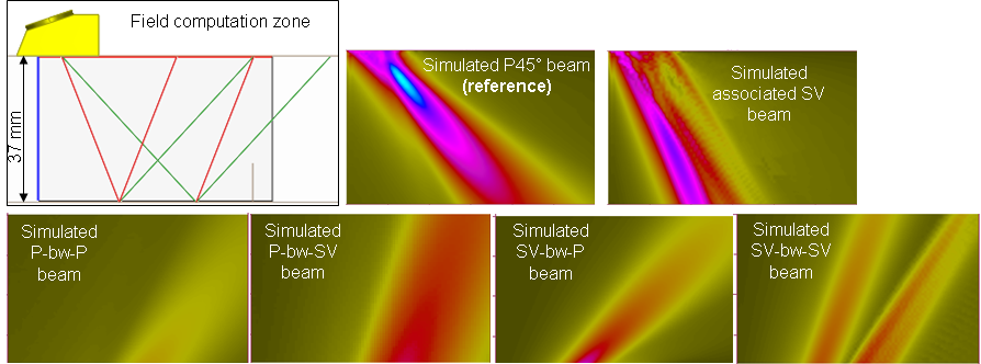
The simulated SV beam is split into two contributions, the second one is not observed experimentally.
This split of the SV beam at the surface is due to the limitations of the beam calculation model. The model using the pencil method (equivalent to standard ray theory) is based on geometrical acoustics: in such an approach, only bulk waves are considered. In the case of P45 waves, a head wave also contributes to the radiated field in SV waves: if the rays radiated by the probe are incident on the specimen surface with an incidence angle close to the longitudinal critical angle, P creeping waves propagating along the entry surface and SV head waves re-radiated in the bulk medium are generated. In addition, such head waves will then interfere with the classical SV refracted bulk waves for an incidence angle very close to the critical one. The value of the incident critical angle depends on the coupling material (plexiglas or water) but it always corresponds to a 33° refracted SV wave angle. In a P45 inspection, although the probe SV focal axis (refracted at 22.8°) is not equal to the critical angle (33°), there are some rays radiated by the probe which are critical or close to due to the probe aperture.
On the B-scans presented here, this beam splitting leads to a clear separation of the SV simulated corner echo. However, this splitting effect doesn’t alter the amplitude of the corner echo (difference less than 2 dB) and the echo is well positioned.
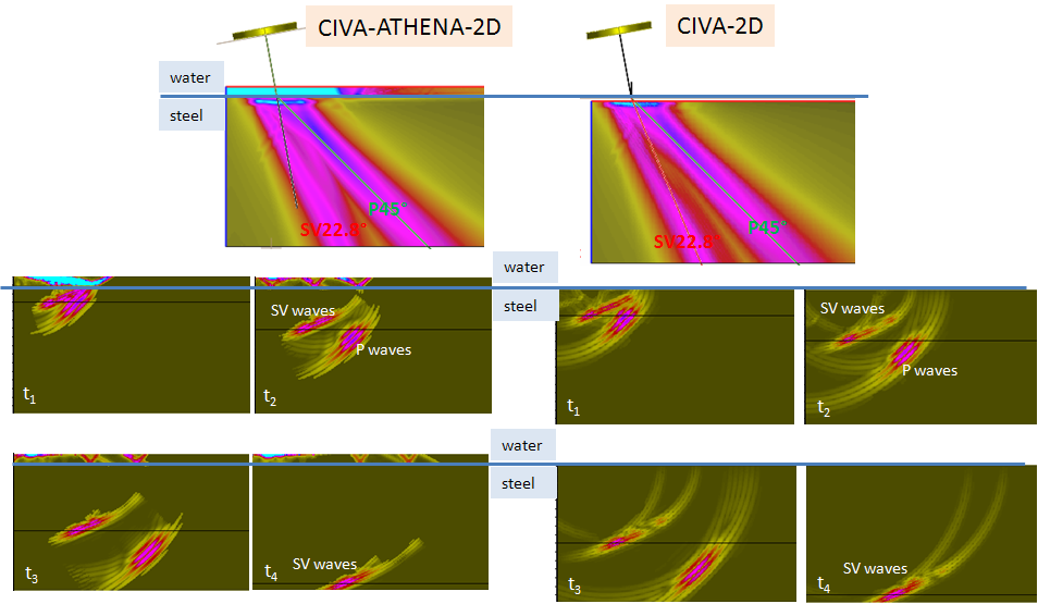
The figure below illustrates this beam division phenomenon. P45 and SV fields radiated in a planar steel specimen by an immersion probe (Ø6.35 mm, 5 MHz) are computed in a zone represented on the 2 images on top of the figure. Two different calculations are performed:
- the field refracted from the water to the specimen is computed with CIVA-ATHENA2D (2D-finite element code coupled with CIVA).
- the field refracted from the water to the specimen is computed with CIVA2D (CIVA with the 2D options for both the field and the defect).
The 8 images displayed on the figure (bottom) represent for each point of the zone, the amplitudes of the fields propagated in the specimen at a given propagation time (ti). The 4 images at left are obtained with ATHENA2D and the 4 other with CIVA2D.
The comparison of these images shows that the P waves and SV waves relative amplitudes are almost the same. But the split of the CIVA-2D SV beam is not observed for the ATHENA2D-2D beam.
The CIVA development team is working on modes transmission around the critical angle in order to improve the existing models in CIVA. The CIVA development team is working on modes transmission around the critical angle in order to improve the existing models in CIVA.
Back to Corner Echoes with P mode
Back to Corner Echoes