This validation case is the result of the study of a working group of COFREND (French Confederation for Non-Destructive Testing). This group "modeling of Eddy currents" aims at proposing benchmarks gathering simulations and experiments results allowing the validation of Eddy currents simulation codes.
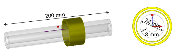
specimen
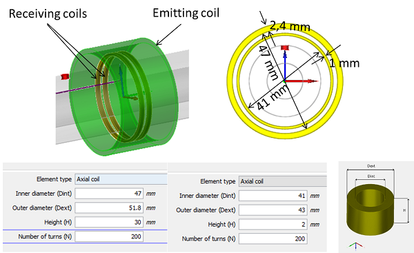
probe
In this study, two inspection configurations are involved. In the first case, the tube is correctly centered in the coil, which corresponds to the optimum inspection configuration. In the second case, the axis of the coil is off-centered by 2 mm with respect to the axis of the tube, as it can be seen below. This shift is usually caused by the vibrations of the tube.
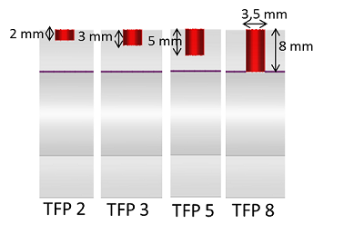
flaws
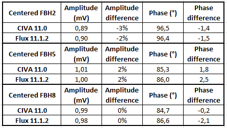
experiments/simulations comparisons
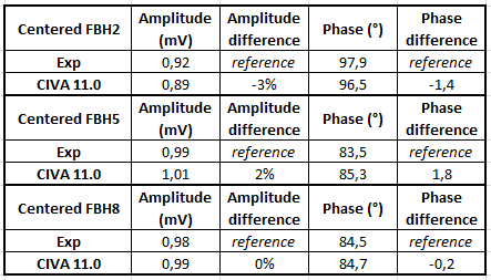
CIVA and experiment Lissajous curves are plotted and superimposed below for each FBH:
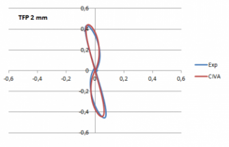
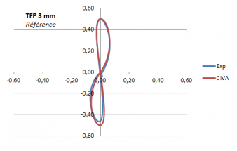
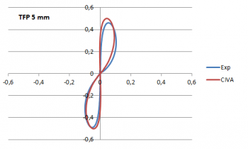
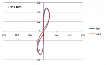
These Lissajous curves confirm the good agreement CIVA / experiment observed in the table of comparisons.
Comparisons between codes
The results obtained with the off-centered coil with respect to the axis of the tube are gathered in the table below. In this case only the CIVA and Flux codes are compared, there are no experimental references but the previous results show that the simulations results are reliable compared to the experiment.
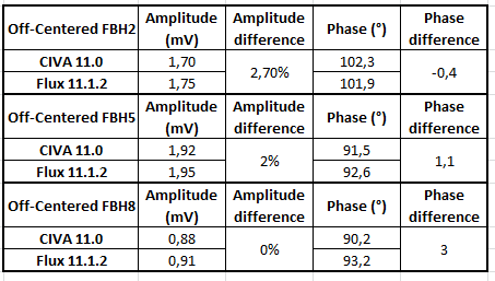
These results show that CIVA and Flux are in agreement, with a maximum of 3% difference in amplitude and 2.5 ° in phase.
These results were published at the ECNDT congress in 2014 article in the Working Group COFREND "Eddy Current NDT modeling": Benchmarks for validation and improving simulation codes acceptation.
Go back to TUBE INSPECTION WITH A ROTATING PROBE
Go back to TUBES