
RT – Step wedge – Experimental protocol
Summary
Two test scenarios were used, depending on whether the detector used was a flat panel or an image plate.
Step wedges radiographed
The wedges studied are flat metal plates (made of Dural and ferritic steel), with regularly spaced but non-constant steps, as well as two sets of holes, also regularly spaced but of different depths and diameters.
The dimensions of each wedge are:
- 200 mm length,
- 120 mm width,
- 10 mm thick for the ferritic steel wedge and 9.6 mm for the Dural one.
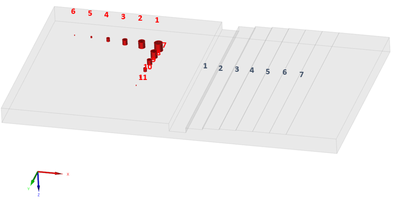
3D view of the wedge
The depths of the holes and thickness of the steps are noted below. Unfilled dimensions are those for which it was impossible to make the measurement (hole diameter too small or below the resolution of the measuring device).
| Thickness measured: wedge made of Dural (mm) | Thickness measured: wedge made of Ferritic steel (mm) | |
| Hole n°1 | 6.0 | 5.2 |
| Hole n°2 | 4.7 | 3.9 |
| Hole n°3 | 3.6 | 3.4 |
| Hole n°4 | 2.3 | 1.8 |
| Hole n°5 | – | – |
| Hole n°6 | – | – |
| Hole n°7 | 4.6 | 4 |
| Hole n°8 | 3.5 | 3.4 |
| Hole n°9 | 2.4 | 1.9 |
| Hole n°10 | – | – |
| Hole n°11 | – | – |
| Step n°1 | 5 | 5.3 |
| Step n°2 | 2 | 2.2 |
| Step n°3 | 1 | 1.2 |
| Step n°4 | 0.5 | 0.4 |
| Step n°5 | 0.2 | 0.3 |
| Step n°6 | 0.1 | 0.2 |
| Step n°7 | – | – |
Densities were measured at 2.76 gcm-3 for the Dural wedge and 7.87 gcm-3 for the ferritic steel one.
Measuring setup for the flat panel detectors
The measurement setup used for acquisitions using the flat panel is shown below.
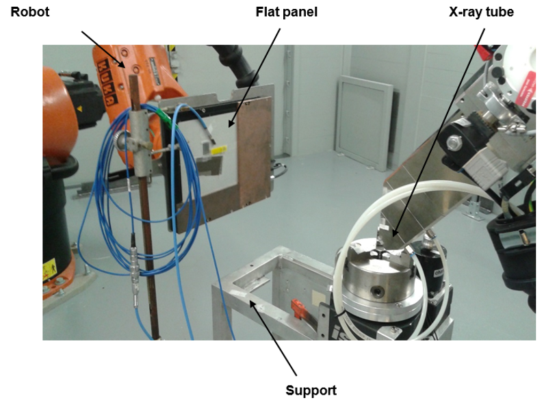
Measuring setup for flat panel detectors
It consists of a support for positioning the specimens to be radiographed, around which two robots position the X-ray tube and the detector. The source is a micro-focus (2 μm) X-ray tube (VISCOM) whose operating voltage is adjustable from 30 kV to 225 kV for a maximum operating power of 320 W. The detector is a flat panel (PERKIN-ELMER, reference XRD 0822 AP). It consists of a several hundred microns thick CsI scintillator, deposited on a 1024 x 1024 photodiode array with a surface area of 200 x 200 μm. The photosensitive surface of the detector is protected by a 750 μm thick aluminum plate.
The acquisitions on the Dural wedge were carried out with an acceleration voltage of 100 kV and an intensity of 800 μA. In addition to the 1 mm aluminum filter integrated into the VISCOM generator, a second 1 mm thick aluminum filter was used. The wedge is positioned against the detector, and the source−detector distance set at 60 cm.
Acquisitions on the ferritic steel wedge were carried out with an acceleration voltage of 200 kV and an intensity of 800 μA. In addition to the 1 mm aluminum filter integrated in the VISCOM generator, a second 1.2 mm thick copper filter was used. The wedge is positioned against the detector, and the source−detector distance set at 60 cm.
Each acquisition was corrected by a black image obtained by averaging 60 acquisitions without irradiation, so that the intrinsic noise of the detector is negligible compared to the gray level measured at any point. The remanence of the detector was taken into account by making these acquisitions before irradiation. The uniformity of the detector response, measured at approximately 1%, has not been corrected.
The standard deviations on the average response were calculated by analyzing the gray-scale distribution (over a region of interest) of the difference of two images successively obtained under identical conditions and multiplying the result by a factor √2 (var (XY) = var (X) + var (Y)) for two independent random variables. In this way, the systematic sensitivity defects of the sensor are eliminated in the estimation of the measurement noise.
Measuring setup for image plate detectors
The measurement setup used for acquisitions using the image plate is shown below.
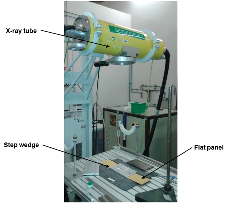
Measuring setup for image plate detectors
The X-ray tube used (YXLON model Y.TU 450-D09) provides photons up to 450 keV, with a power of 1.5 kW; Its focus has a diameter of 400 μm. It is supported by a bracket and oriented so that the axis of irradiation is vertical. The wedge to be radiographed, placed directly on the image plate, is held in position on this axis. The image plates used are DÜRR NDT, model 10×48 HR (high-resolution version). After irradiation, they are digitized using a GE FS50B scanner. The resolution of this digitizing device is 493 dots per inch, or about 50 μm.
For the Dural wedge, the acceleration voltage of the generator was set at 100 kV, its current at 500 μA. An aluminum filter of 3 mm thickness is positioned between the generator and the wedge. The source−detector distance is set at 60 cm.
Acquisitions for the ferritic steel wedge were obtained with an acceleration voltage of 200 kV, the other parameters remaining constant.
The evaluation of the measurement noise is made only from a single acquisition. The standard deviation on the detector response, measured in a region of interest, therefore also takes into account the systematic effects (scratches, flatness of the wedge, local variation in sensitivity of the detector), and measurement noise is therefore overestimated.
Continue to Modeling using CIVA