The TOFD DESCRIPTION
DeFINITIONS
PCS
The distance between the two probes is called PCS (Probe Center Space). In immersion, the PCS corresponds to the distance between each one of the beam impact point on the specimen. In contact configuration, it is the distance between the emergence beam points on the specimen.
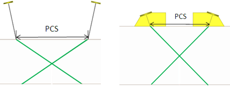
The PCS value influences the ultrasonic beams crossing point in the specimen. The larger is the PCS, the deeper is the crossing point.
A variation of the PCS goes also along with a variation of the ultrasonic beam incidence angle relative to the flaw’s normal.
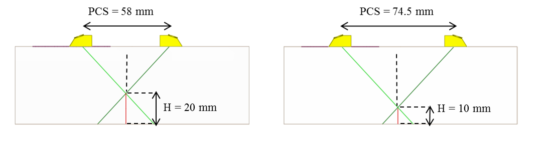
Crossing Point
The theoretical axis of longitudinal waves, refracted in the specimen by the transmitting transducer, crosses the one from the receiver at a point which will be called hereinafter the “P axes crossing point”. This point and the associated “P axes crossing point depth” are shown on figure below.
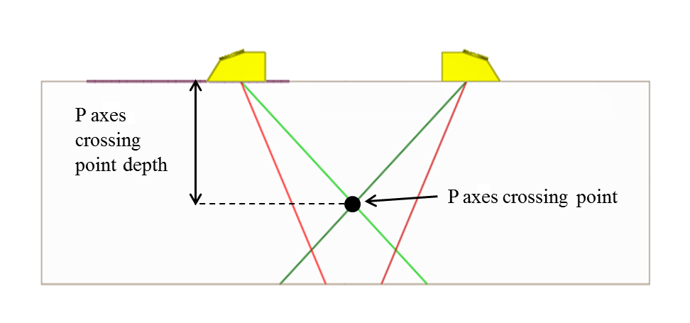
The same way, the “SV axes crossing point” is defined as the point where the theoretical axes of transversal waves refracted in the specimen by the transmitting transducer crosses the one from the receiver.
refraction and incidence angles on the top and bottom edge of the notch
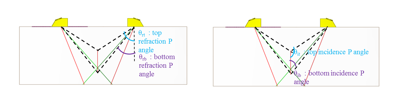
The refraction angle between the normal to the transducer and the ray from the impact point of the transmitting/receiving transducer to the top/the bottom of the flaw is called “top/bottom refraction angle”. From these angles, top and bottom incidence angles can be defined. These angles are often used in TOFD and are represented on the figure below.
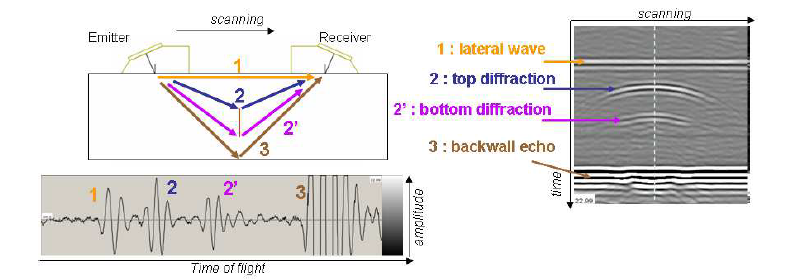
Time of flight
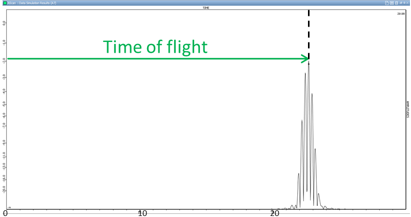
The time of flight corresponds to the propagation time from the transmitter to the receiver. In this study, the times of flight are determined from the absolutes ones, measured at the maximum of the rectified signal, as shown on the following figure. The start time corresponds to the moment when ultrasounds are emitted by the piezo-electric crystal. Then, the time of flight takes into account (in CIVA and in the experiments) the waves propagation time in the wedge, called “probe delay”.
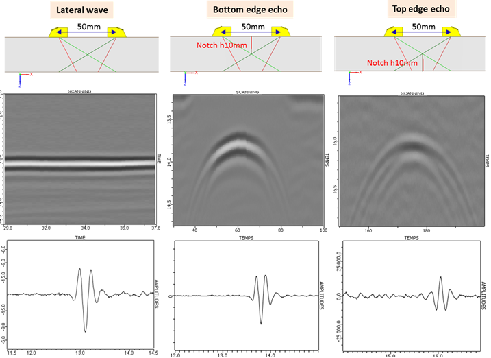
echoes phase on the top and the bottom edge of the flaw
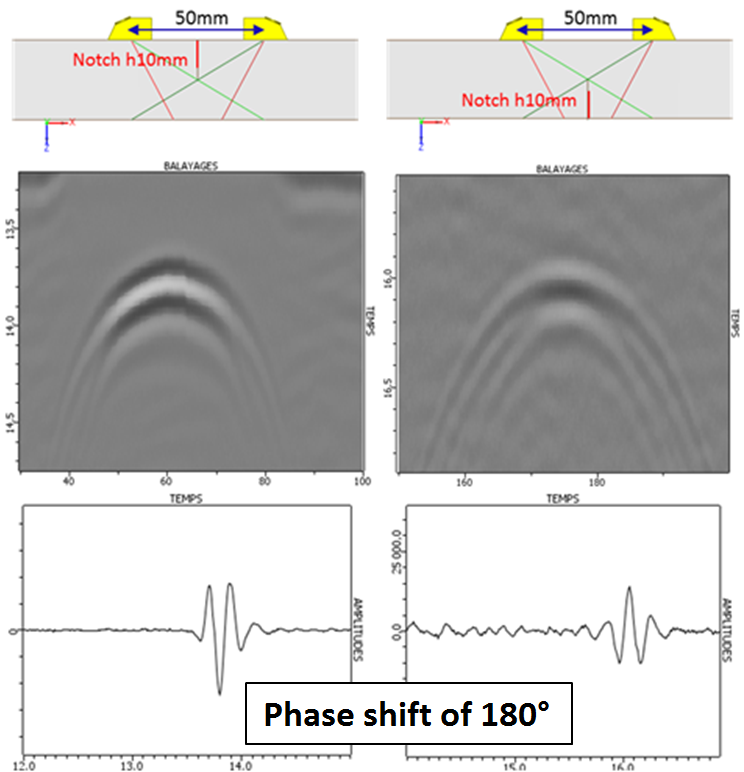
The top and bottom edges diffraction echoes are generally in phase opposition. This behavior is reproduced in simulation. It will be highlighted during the validation.
Continue to Presentation of the studied configurations
Back to TOFD