Experimental and simulation settings
Experimental set-up
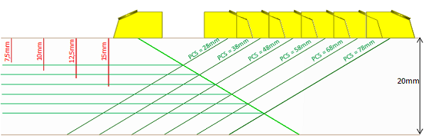
The figure below shows the mock-up used for the study. This is a rectangular block made of ferritic steel and of 30mm height. The specimen contains 4 vertical planar flaws of 7.5mm to 15mm height, 15mm extension and 0.2 aperture
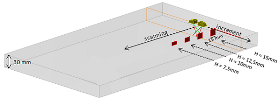
The probes used for inspection have 6.35mm diameter, 5MHz central frequency and generate LW45°, LW60° and LW70° in the mock-up.
For each couple of probe, the L bottom edge diffraction echo of the 15mm, 12.5mm, 10mm and 7.5 mm high notches has been measured with a PCS increasing slowly so the 2 following parameters vary slowly too:
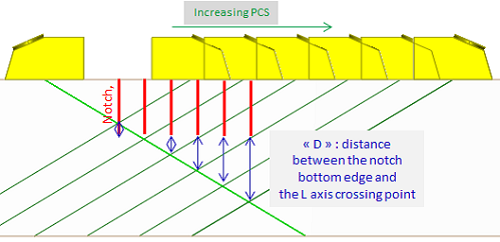
- The distance « |D| », between the crossing point of the probes axes at the base of the notch and the bottom edge of it (see figure below). Note that “D” can be negative.
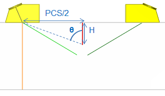
- The incidence angle θ of L waves on the bottom edge of the notch (see figure below)
Uncertainties measurements
See the chapter "uncertainties" chapter here: uncertainties
Simulation parameters
Refer to the page "Presentation of the studied configurations"
Reference amplitude
The method used for the measurement of the amplitude of reference is explained here: amplitude of reference (see amplitude and time of flight comparisons chapter).
For each couple of transducers (LW45, LW60 and LW70) the maximum amplitudes of bottom edge diffraction echoes of a notch of a given height will be plotted according to:
- The PCS. A blue dotted line indicates the PCS for which the depth of the L axes crossing point and of the bottom edge of the notch are the same.
- The incidence angle θ of L waves on the bottom edge of the notch
- The distance « D » between the crossing point of the probes axes at the top of the notch and the bottom edge of the notch.
Comparison of experimental and simulated amplitudes
LW45° probes
The refraction angle measured in the specimen of the L wave transmitted by each probe is 44.5°. The reference amplitude is the maximum amplitude of the L direct echo of a 2 mm diameter SDH located at 20mm depth when the PCS is 38mm.
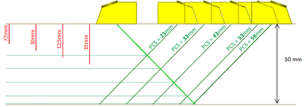
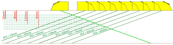
The 4 notches and the probes L axes for different PCS are presented on the figure below in order to visualize the depth of the axes crossing points and the bottom edge depth of the notches
Results for the 15mm high notch
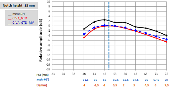
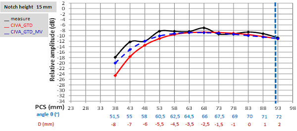
The experimental and simulated results obtained for the 15mm high notch are presented on the figure below.
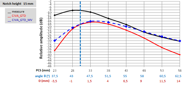
The comparison of the experimental curve (in black) with the CIVA_GTD simulated curve (in red) shows that the simulated amplitudes are always lower than the experimental ones. The most important difference (24 dB) is measured for the shortest PCS (23mm).
The comparison of simulated results obtained with CIVA_GTD and CIVA_GTD_MV shows that both models provide similar results when the distance |D| between the bottom edge depth and the crossing point is between -1mm and 6.5mm. Beyond these limits, the differences in amplitudes between both models are larger than 3 dB. This result is in agreement with the beam approximation in CIVA used during the calculation of the incident beam interaction with the notch (see further). The differences betwwen CIVA_GTD and CIVA_GTD_MV appear when |D| increases, i.e. when the approximated description of the beam is no longer valid
It can be seen that the amplitudes obtained with CIVA_GTD_MV are close to experimental amplitudes for incidence angles θ larger than 51.5°. For the other incidence angles, the simulated amplitudes are lower than experimental ones.
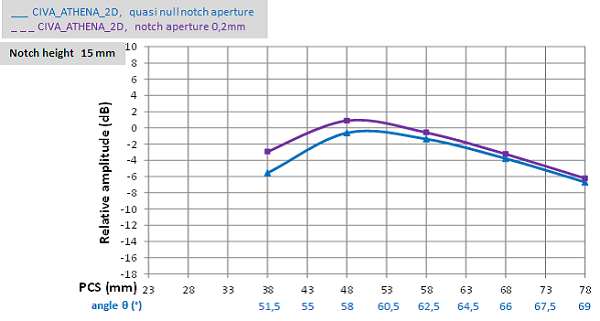
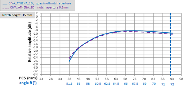
The results from CIVA_ATHENA_2D simulations are presented below. They allow to study the influence of the notch aperture on the bottom edge echo amplitude.
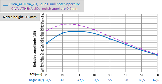
It can be seen that for incidence angles θ less than 51.5°, the amplitudes simulated with CIVA_ATHENA_2D for notches with 0.2mm aperture are larger than the amplitudes of null aperture notches. Because at these angles CIVA_GTD_MV underestimates the amplitudes relatively to the experiment, taking into account the real aperture of the notches, in “3D” would reduce this underestimation.
For incidence angles θ larger than 51.5°, taking into account the notch aperture does not change significantly the results. The amplitudes are close to each other. For these incidence angles, the good agreement between CIVA_GTD_MV and experience would not be changed if the real aperture of the notches is taken into account.
Results for the 12.5mm high notch
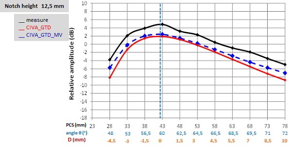
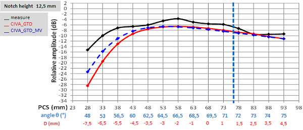
The experimental and simulated results obtained for the 12.5mm high notch are presented on the figure below.
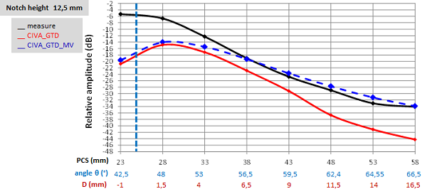
The comparison of the experimental curve (in black) with the CIVA_GTD simulated curve (in red) shows that the simulated amplitudes are always lower than the experimental ones. The most important difference (15 dB) is measured for the shortest PCS (23mm).
The comparison of simulated results obtained with CIVA_GTD and CIVA_GTD_MV shows that both models provide similar results when the distance |D| between the depth of the lower tip of the notch and the crossing point is lower than 5mm. This result is in agreement with the beam approximation in CIVA used during the calculation of the incident beam interaction with the notch (see further). The differences between CIVA_GTD and CIVA_GTD_MV appear when |D| increases, i.e. when the approximated description of the beam is no longer valid.
It can also be seen that the amplitudes obtained with CIVA_GTD_MV are close to experimental amplitudes for incidence angles θ larger than 53°. For other incidence angles, the simulated amplitudes are weaker than experimental ones.
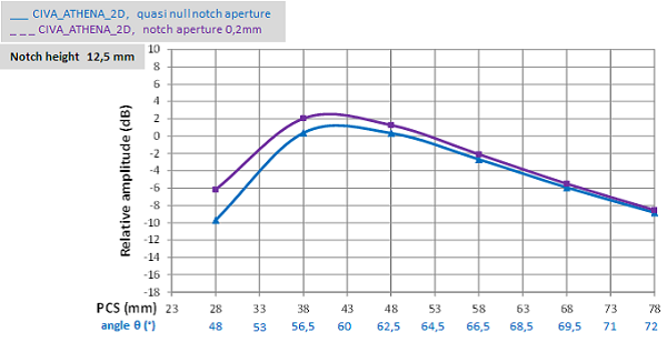
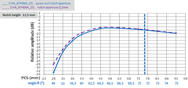
The results from CIVA_ATHENA_2D are presented below. They show the influence of the notch aperture on the amplitude of the bottom edge echo.
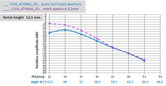
It can be seen that for incidence angles θ lower than 53°, the amplitudes of notches with 0.2mm aperture simulated with CIVA_ATHENA_2D are higher than the amplitudes of null aperture notches. Because at these angles CIVA_GTD_MV underestimates the amplitudes relatively to the experiment, taking into account the real aperture of the notches, in “3D” would reduce this underestimation.
For incidence angles θ larger than 53°, taking into account the notch aperture does not change significantly the results. The amplitudes are close to each other. For these incidence angles, the good agreement between CIVA_GTD_MV and experience would not be changed by taking into account the real aperture of the notches.
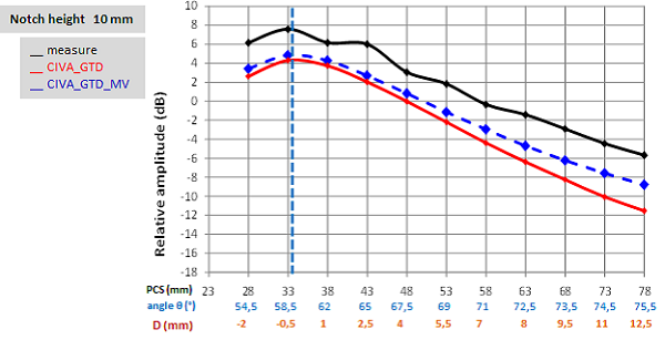
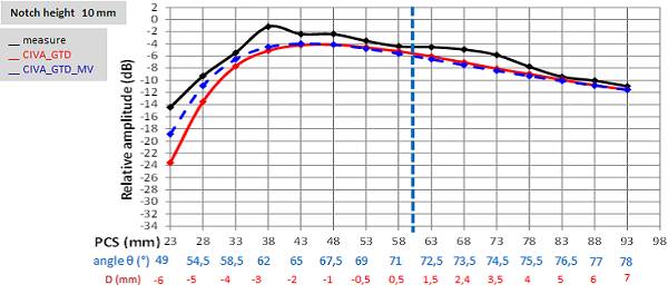
Results for the 10mm high notch
The experimental and simulated results obtained for the 12.5mm high notch are presented on the figure below.
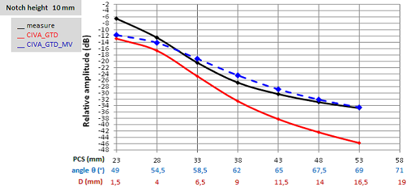
The comparison of the experimental curve (in black) with the CIVA_GTD simulated curve (in red) shows that the simulated amplitudes are always lower than the experimental ones. The most important difference (12 dB) is measured for the largest PCS (53mm).
The comparison of simulated results obtained with CIVA_GTD and CIVA_GTD_MV shows that both models provide similar results (less than 3dB difference) when the distance |D| between the depth of the bottom edge and the crossing point is shorter than 4 mm. This result is in agreement with the beam approximation in CIVA used during the calculation of the incident beam interaction with the notch (see further). The differences between CIVA_GTD and CIVA_GTD_MV appear when |D| increases, i.e. when the approximated description of the beam is no longer valid.
It can be seen that the amplitudes obtained with CIVA_GTD_MV are close to experimental amplitudes for incidence angles θ larger than 53°. For other incidence angles, the simulated amplitudes are weaker than experimental ones.
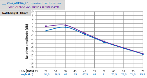
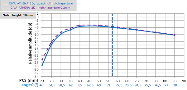
The results from CIVA_ATHENA_2D are presented below. They allow to see the influence of the notch aperture on the bottom edge echo amplitude.
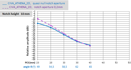
It can be seen that for incidence angles θ lower than 50°, the amplitudes of notches with 0.2mm aperture simulated with CIVA_ATHENA_2D are higher than the amplitudes of null aperture notches. Because for theses angles CIVA_GTD_MV underestimates the simulated amplitudes relatively to the experiment, taking into account the real aperture of the notches, in “3D”, would reduce this underestimation.
For incidence angles θ larger than 50°, taking into account the notch aperture does not change significantly the results. The amplitudes are close to each other. For these incidence angles, the good agreement between CIVA_GTD_MV and experience would not be changed if the real aperture of the notches is taken into account.
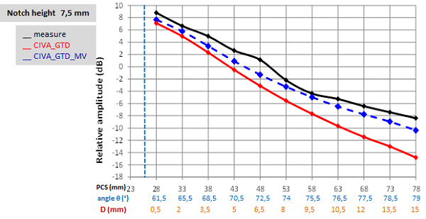
Results for the 7.5mm high notch
The experimental and simulated results obtained for the 7.5 mm high notch are presented on the figure below.
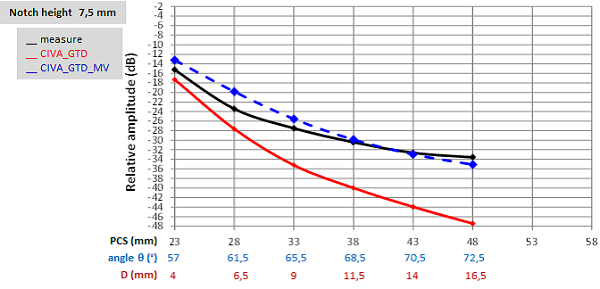
The comparison of the experimental curve (in black) with the CIVA_GTD simulated curve (in red) shows that the simulated amplitudes are always lower than the experimental ones. The most important difference (14 dB) is measured for the largest PCS (53mm).
The comparison of simulated results obtained with CIVA_GTD and CIVA_GTD_MV shows that amplitudes from CIVA_GTD_MV are always higher than the ones with CIVA_GTD when |D| is longer than 4 mm.
We can also see that the amplitudes obtained with CIVA_GTD_MV are close to experimental ones for incidence angles θ larger than 57°.
Conclusion on the LW45° detection
In order to obtain GTD simulation results close to the experimental ones it is necessary to use a more specific description of the field and / or take into account the notch aperture through a CIVA ATHENA 2D simulation.
LW60° probes
From the measurements results, the refraction angle in the specimen of the L wave transmitted by each probe is 59°. The reference amplitude is the maximum amplitude of the L direct echo of a 2 mm diameter SDH located at 20mm depth when the PCS is 68mm.
The 4 notches and the L axes for different PCS are presented on the figure below in order to visualize the axes crossing points depths and the notches bottom edge depths.
Results for the 15mm high notch
The experimental and simulated results obtained for the 15 mm high notch are presented on the figure below.
The comparison of the experimental curve (in black) with the CIVA_GTD simulated curve (in red) shows that the simulated amplitudes are always lower than the experimental ones. The underestimation is constant and equal to 3 to 4 dB.
Furthermore, it can be seen that the maximal amplitude is measured when the PCS is close to the PCS of reference. At this PCS, the probes L axes cross themselves at the depth of the lower tip of the notch (symbolized by the vertical blue dotted line).
The comparison of simulated results obtained with CIVA_GTD and CIVA_GTD_MV shows that both models provide similar results whatever the distance |D| between the lower tip of the notch depth and the crossing point is.
The results from CIVA_ATHENA_2D are presented below. They show the influence of the notch aperture on the amplitude of the bottom edge echo.
Taking into account the notch aperture allows to measure higher diffraction echoes amplitudes especially for incidence angles θ lower than 60.5°. It seems possible to reduce the difference between simulation with CIVA_GTD_MV and experiment (for incidence angles lower than 62°) by taking into account the notch aperture. However, such a “3D” model is not yet available. Moreover, for incidence angles larger than 60.5°, the underestimation of 2 to 3 dB of the diffraction echo simulated with CIVA_GTD_MV would not disappear although it is acceptable regarding the measurement uncertainty.
Results for the 12.5mm high notch
The experimental and simulated results obtained for the 12.5 mm high notch are presented on the figure below.
The comparison of the experimental curve (in black) with the CIVA_GTD simulated curve (in red) shows that the simulated amplitudes are always weaker than the experimental ones. The underestimation is constant and equal to 3 to 4 dB.
Furthermore, it can be seen that the maximal amplitude is measured when the PCS is close to the reference symbolized by the vertical blue dotted line.
The comparison of simulated results obtained with CIVA_GTD and CIVA_GTD_MV shows that both models provide similar results whatever the distance |D| between the lower tip depth and the crossing point is.
The results from CIVA_ATHENA_2D are presented below. They show the influence of the notch aperture on the bottom edge echo amplitude.
Taking into account the notch aperture allows to measure higher diffraction echoes amplitudes especially for incidence angles θ lower than 60°. It seems possible to reduce the difference between simulations with CIVA_GTD_MV (for incidence angles lower than 60°) by taking into account the notch aperture. However such a “3D” model is not yet available. Moreover, for incidence angles larger than 60.5°, the underestimation of 2 to 3 dB of the diffraction echo simulated with CIVA_GTD_MV would not disappear although it is acceptable regarding the measurement uncertainty.
Results for the 10mm high notch
The experimental and simulated results obtained for the 10 mm high notch are presented on the figure below.
The comparison of the experimental curve (in black) with the CIVA_GTD simulated curve (in red) shows that the simulated amplitudes are always weaker than the experimental ones. The underestimation increases with PCS. It is equal to 3 to 4 dB for the shortest PCS and equal to 6 to 7 dB for the longest PCS.
Furthermore, it can be seen that the maximal amplitude is measured when the PCS is close to the reference symbolized by the vertical blue dotted line. This corresponds to the PCS for which the probes L axes cross themselves at the bottom edge of the notch.
The comparison of simulated results obtained with CIVA_GTD and CIVA_GTD_MV shows that both models provide similar results until the distance |D| is equal to 8mm. Beyond this value, the CIVA_GTD_MV amplitudes are higher than the ones obtained with CIVA_GTD.
The results from CIVA_ATHENA_2D are presented below. Theyshow the influence of the notch aperture on the bottom edge echo amplitude.
Taking into account the notch aperture allows to measure higher diffraction echoes amplitudes especially for incidence angles θ lower than 62°. It seems possible to reduce the difference between simulations with CIVA_GTD_MV (for incidence angles lower than 62°) by taking into account the notch aperture. However such a “3D” model is not yet available. Moreover, for incidence angles larger than 62°, the underestimation of 2 to 3 dB of the diffraction echo simulated with CIVA_GTD_MV would not disappear but it is acceptable regarding the measurement uncertainty.
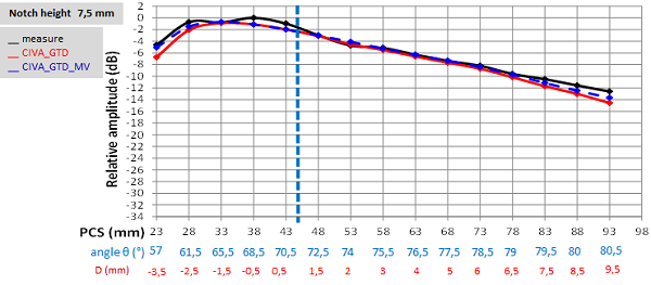
Results for the 7.5mm high notch
The experimental and simulated results obtained for the 7.5 mm high notch are presented on the figure below.
The comparison of the experimental curve (in black) with the CIVA_GTD simulated curve (in red) shows that the simulated amplitudes are always weaker than the experimental ones. The underestimation increases with PCS. It is equal to 3 to 4 dB for the shortest PCS and equal to 6 to 7 dB for the longest PCS (7 dB difference when PCS=78mm).
The comparison of simulated results obtained with CIVA_GTD and CIVA_GTD_MV shows that both models provide similar results until the distance |D| is equal to 6mm. Beyond this value, the CIVA_GTD_MV amplitudes are higher than the ones obtained with CIVA_GTD.
Conclusion on the LW60° detection
To obtain GTD simulation results close to the experimental ones, it is necessary to use a more specific description of the field and / or take into account the notch aperture through a CIVA ATHENA 2D simulation.
LW70° probes
From the measurements, the refraction angle in the specimen of the L wave transmitted by each probe is 70°. The reference amplitude is the maximum amplitude of the L direct echo of a 0.7 mm diameter SDH located at 10mm depth when the PCS is 53mm.
The 4 notches and L axes for different PCS are presented on the figure below in order to visualize the axes crossing points depths and the notches bottom edge depth.
Results for the 15mm high notch
The experimental and simulated results obtained for the 15 mm high notch are presented on the figure below.
The comparison of the experimental curve (in black) with the CIVA_GTD simulated curve (in red) shows that the simulated amplitudes are close to experimental ones expect for the shortest PCS. For these ones, the simulated amplitude is weaker than experimental one.
The comparison of simulated results obtained with CIVA_GTD and CIVA_GTD_MV shows that both models provide similar results when the distance |D| between the bottom edge depth and the crossing point is longer than -7mm. Below this value, the CIVA_GTD_MV amplitudes are higher than the ones obtained with CIVA_GTD. In other words, CIVA_GTD_MV amplitudes are closer to experimental ones than CIVA_GTD amplitudes.
The results from CIVA_ATHENA_2D are presented below. They show the influence of the notch aperture on the bottom edge echo amplitude.
Taking into account the notch aperture has almost no influence on the simulated amplitudes. Indeed, for LW70° inspection the incidence angle is larger than for LW45° or LW60° inspections, thus the apparition of creeping waves along the notch aperture is not favored.
Results for the 12.5mm high notch
The experimental and simulated results obtained for the 12.5 mm high notch are presented on the figure below.
The comparison of the experimental curve (in black) with the CIVA_GTD simulated curve (in red) shows that the simulated amplitudes are close to experimental ones expect for the shortest PCSs. For these ones, the simulated amplitude is weaker than experimental one.
The comparison of simulated results obtained with CIVA_GTD and CIVA_GTD_MV shows that both models provide similar results when the distance |D| between the bottom edge depth and the crossing point is longer than -6mm. Below this value, the CIVA_GTD_MV amplitudes are higher than the ones obtained with CIVA_GTD. In other words, CIVA_GTD_MV amplitudes are closer to experimental ones than CIVA_GTD amplitudes.
The results from CIVA_ATHENA_2D are presented below. They show the influence of the notch aperture on the bottom edge echo amplitude.
Taking into account the notch aperture has almost no influence on the simulated amplitudes. Indeed, for LW70° inspection the incidence angle is larger than for LW45° or LW60° inspections, thus the apparition of creeping waves along the notch aperture is not favored.
Results for the 10mm high notch
The experimental and simulated results obtained for the 10 mm high notch are presented on the figure below.
The comparison of the experimental curve (in black) with the CIVA_GTD simulated curve (in red) shows that the simulated amplitudes are close to experimental ones expect for the shortest PCSs. For these ones, the simulated amplitude is weaker than experimental one.
The comparison of simulated results obtained with CIVA_GTD and CIVA_GTD_MV shows that both models provide similar results when the distance |D| between the bottom edge depth and the crossing point is longer than -5mm. Below this value, the CIVA_GTD_MV amplitudes are higher than the ones obtained with CIVA_GTD. In other words, CIVA_GTD_MV amplitudes are closer to experimental ones than CIVA_GTD amplitudes.
The results from CIVA_ATHENA_2D are presented below. They show the influence of the notch aperture on the bottom edge echo amplitude.
Taking into account the notch aperture has almost no influence on the simulated amplitudes. Indeed, for LW70° inspection the incidence angle is larger than for LW45° or LW60° inspections, thus the apparition of creeping waves along the notch aperture is not favored.
Results for the 7.5mm high notch
The experimental and simulated results obtained for the 7.5 mm high notch are presented on the figure below.
The comparison of the experimental curve (in black) with the CIVA_GTD simulated curve (in red) shows that the simulated amplitudes are in good agreement with experimental ones for all PCSs.
Conclusion on the LW70° detection
On the overall, simulation results are in good agreement with experimental ones, especially for the largest PCS..
General conclusion on the amplitudes comparison
Finally, the results show that for all LW45°, LW60° and LW70° inspections the amplitudes of bottom edge echoes of notches predicted by CIVA are in fairly good agreement with experiment for most of the configurations studied. To see this, two methods were used:
- Calculating the bottom edge echo of a notch of null aperture with the GTD algorithm
- Calculating the bottom edge echo of a notch with a phased-array probe (equivalent to the original single element probe) with the CIVA_GTD_MV model in order to use a more precise description of the incident beam on the tip and aperture of the notch. However, it should be noted that this calculation cannot be realized with CIVA 11.0a if the user has no access to the execution variable called "MULTI-VOIES".
The reason why some simulations performed with CIVA_GTD and CVA_GTD_MV do not lead to a good agreement with experiment is that the notch aperture was not taken into account when calculating the lower tip echo. Calculations with CIVA_ATHENA_2D allowed to lead to this hypothesis. However, these simulations should be confirmed in “3D” when a model allows it.
Explanations of the differences between experiments and the GDT model
Approximation of the beam in CIVA
In TOFD, the calculation of a notch bottom edge diffraction echo uses a simplified description of the ultrasonic beam transmitted by each single element. The simplification concerns the temporal shape of the signal, the incidence direction, the amplitude, the phase and the time of flight. Thus, the validity of this approximation depends on the position of the notch tip in the field of the 2 probes. The approximation is not available when the depth of the lower tip of the notch is far from the depth of the axes crossing point (i.e. when “D” is long, see figure below) and when the bottom edge is not in the intense zones of the beam
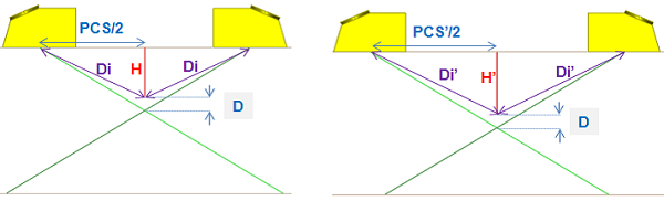
Furthermore, for a specific distance « D », the validity of the approximated description of the beam is reduced when the distance « Di » between the bottom edge and the impact point of the probe is short. It is the case of the configuration on the left of the figure below. This goes with the already known problems of CIVA simulations in the near field.
The runtime variable « MULTI VOIES » of CIVA allows to avoid this approximation. Each single probe is replaced by a phased-array probe of 249 elements with the same shape. This allows a more precise description of the beam used by the GTD model when calculating the interaction with the notches. Indeed, with single element probes it is the global ultrasonic beam that is simplified whereas with phased-array probes it is each elementary beam which is simplified. The runtime variable “MULTI-VOIES” allows to calculate the bottom edge response by taking into account at each point of the edge the 249 elementary beams instead of the global ultrasonic beam. This allows a more precise description of the beam.
Notch aperture not taken into account
The figure below shows the propagation of creeping waves (L and T) along the notch aperture.
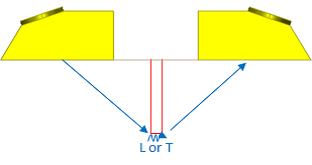
These waves, very close temporally, can change the amplitude of the bottom edge echoes. They appear for small incidence angles θ on the bottom edge, i.e. for short PCS. They are taken into account with the GTD model but only if they have the same time of flight since GTD is available only for null aperture notches.
Thus, CIVA_ATHENA_2D was used in order to take into account these waves for 0.2mm aperture notches. It is the only “2D” model that allows considering the notch aperture. The bottom edge echoes of open notches described with “multifaceted” flaws of 0.2mm rectangular aperture and the echoes of null aperture notches were calculated with this model and compared each other.
Finally, it should be noted that the effects due to the non consideration of the notch aperture may combine with the effects caused by the beam approximation.
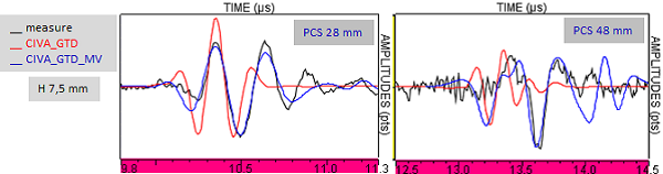
Ascans comparisons
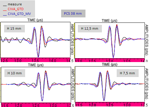
The Ascans comparison shows that when the amplitudes are in good agreement the Ascans arealso in good agreement. The figure below shows the good agreement between the simulated and experimental Ascans for the LW60° inspection with PCS=38mm.
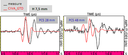
When the amplitudes predicted by CIVA_GTD are not in good agreement with the experimental amplitudes, the Ascan superposition may not be good depending on the cause explaining the amplitude differences. Thus, if the approximated description of the beam is the cause of the differences between experimental and simulated amplitudes, then the simulated and experimental Ascans won’t be in good agreement. The figure below illustrates this behavior for the 7.5 high notch detected in OLW45°.
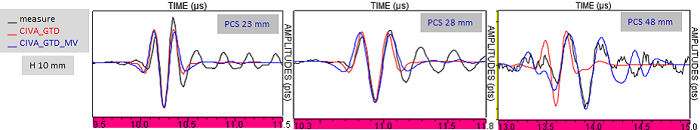
Moreover, when CIVA_GTD Ascans are not in good agreement with experimental Ascans, then the Ascans simulated with CIVA_GTD_MV are most of the time in better in agreement with experimental Ascans than CIVA_GTD Ascans (see figure below for 10mm and 7.5mm high notches detected in OLW45°).
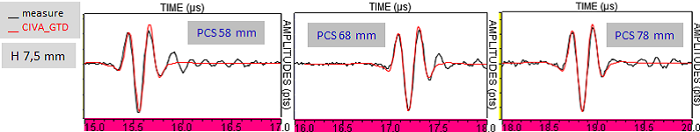
On the contrary, if the cause of the amplitude differences is the non-consideration of the notch aperture, then the simulated and the experimental Ascans are in good agreement. It is illustrated by the figure below for a 7.5mm high notch detected with OLW60°.
Taking into account the notch aperture does not change the Ascans shape. It has been verified by comparison of the Ascans obtained with CIVA_ATHENA_2D.
The figure below shows the Ascans associated with the configurations where considering the notch aperture influences the amplitude of diffraction echoes (OLW60°, 15mm and 12.5mm high notches).
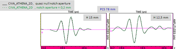
There is a very good agreement between the Ascans with and witout considering the notch aperture.
This has been verified also for configurations where the notch aperture was the cause of the amplitude differences between simulation and experiment (for example: configuration OLW45°).
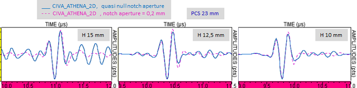
The good agreement of the Ascans obtained with and without considering the notch aperture is certainly due to the fact that the both L and T creeping waves have close time of flights for thin apertures (here 0.2 mm).
Conclusion
- A good agreement between experimental echoes and simulated ones with the GTD model of CIVA11.0a:
- If the crossing point of the probes axes is close to the bottom edge of the notch
- AND if the incidence angle θ of the L waves on the edge is such that the aperture of the notch has no effect on the echo (θ larger than 50°-55° for the 5MHz probes used for this study)
- Differences when the bottom edge depth is far from the depth of the probes axes crossing point or when the angles θ are smaller than 50°-55°. Then, CIVA underestimates the amplitudes comparatively to the experiment. Two options allow to reduce these differences:
- by dispensing with the beam approximation in CIVA for the calculation of the beam / notch interaction. This approximation is no longer valid when the bottom edge is very far from the probes axes crossing point. Simulations with the GTD model + the runtime variable MULTIVOIES (available for internal users only) have shown that bottom edge echoes amplitude predicted by CIVA are higher than those obtained with the GTD algorithm and also closer to the experiment ; the same for the A-scans.
- By taking into account the real notch aperture and by simulating the waves which propagate along this aperture. Taking into account the notch aperture changes the amplitude especially for small incidence angles of the L waves on the bottom edge. Simulations performed with ATHENA_2D and a multi-facet defect describing an opened notch showed that the amplitudes predicted by ATHENA_2D are higher than those of null aperture notches. Thus, we can assume that in "3D", the simulated amplitudes would get closer to experimental ones if the notch aperture is taken into account.
NB1: It should be noted that not considering the notch aperture and the beam approximation does not change the results that already presented a good agreement between simulation and experiment.
NB2: Real notches (not machined) have almost null parture; the GTD model or GTD_MV model + runtime variable MULTIVOIES should lead to accurate simulation of bottom edge echoes.
Continue to Results on the top edge of a vertical notch
Back to TOFD